Kate G. - Jun 27 2025
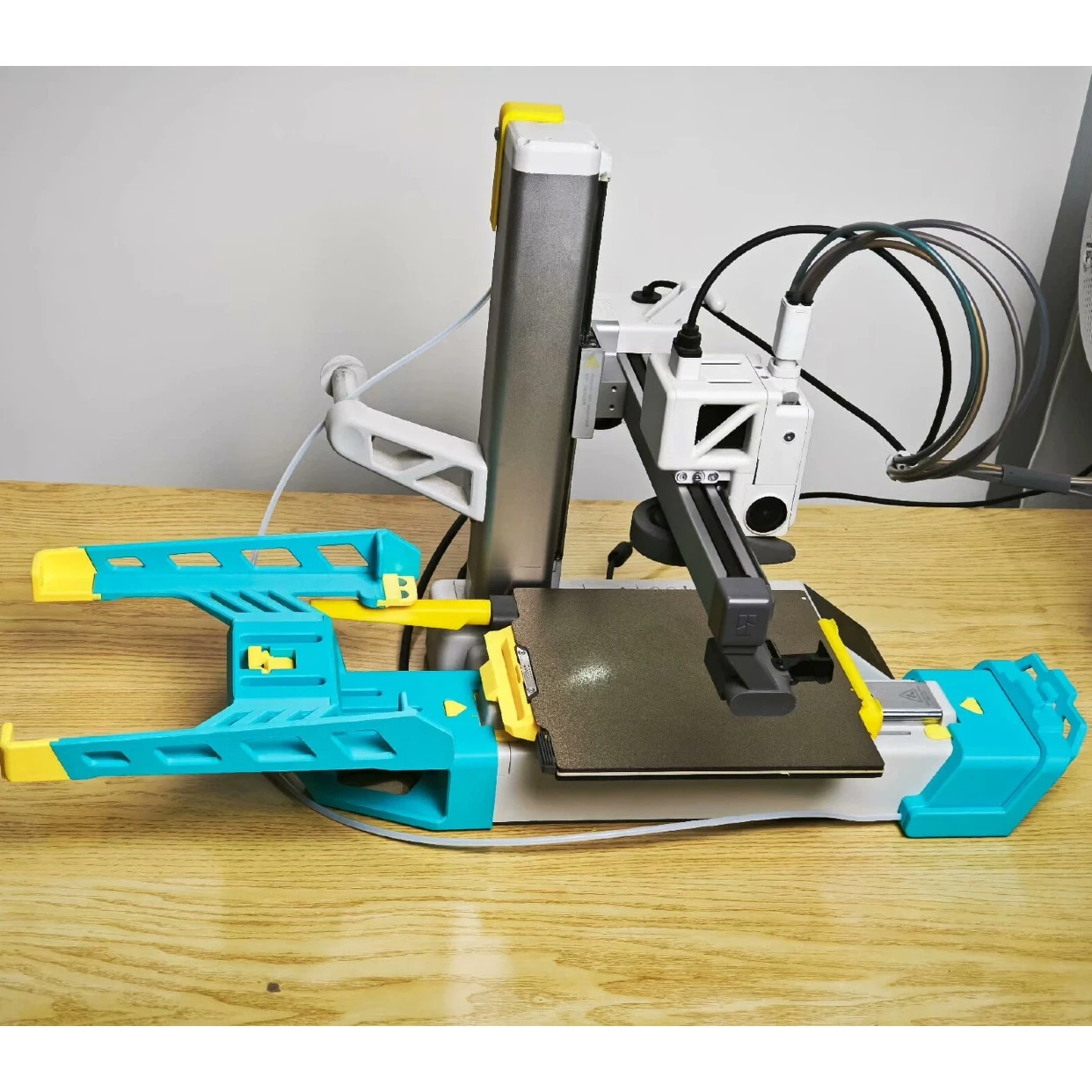
Bambu A1 Auto Swap Tutorial

Assembly Instructions

1·Y-axis hook-type printed component
2·Printing platform tray
3·Cable Tie
4·Y-axis front assembly【Remove the printing board hook.】
5·Z-axis printed parts
6·Z-axis Trigger

1- Installation of the Y-axis hook-type printed component.
Turn the printer over and remove the screws from the bottom of the printer as shown in the diagram.

Install the hook-shaped printed part in the position shown in the diagram and secure it with M3X20 screws.

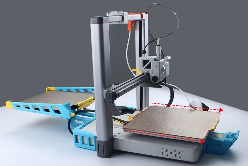
2- Installation of the tray for the printing platform.
Insert according to the direction indicated by the arrows in the diagram, and tighten the two M3*10 screws at the bottom.


Insert according to the direction of the arrows in the diagram and secure with the two M3*10 screws on the side

Insert according to the direction indicated by the arrows in the schematic.


Insert the tray in the direction indicated by the arrows in the schematic.

Note: During installation, slightly lift the rear side and insert in the direction of the arrow. Press down on both sides to ensure that the bottom screws are securely in place.

According to the arrows indicated in the schematic diagram, lightly tighten the four M3*10 screws at the bottom. Please note that these four screws do not need to be fully tightened; simply turn them until they secure the bottom hole positions.

3- Installation of the Cable Tie.
As indicated in the diagram, first install the yellow printed component, then secure the wires. Insert according to the direction of the arrows in the image until you hear a click.


4- To install the Y-axis front assembly
First remove the two original screws from the printer, then tighten the two M3*25 screws indicated by the arrows in the image.


5- Installation of the Z-axis printed parts
Remove the screws from the crossbeam at the back of the extruder and secure the Z-axis print with M3*5 screws.

6- Installation of the Z-axis Trigger
Insert the top beam of the printer according to the direction of the arrow in the image, and push it to the indicated position.


7- Install the printed circuit board holder.
Install the printed circuit board holder. Secure the holder with M3*6 screws.
The fixed clamp STL file is available for self-printing, and it requires the use of PETG for printing.
https://makerworld.com.cn/zh/models/1140084-a1zi-dong-huan-ban-tao-jian-da-yin-ban-gua-gou#profileId-1207166
Note: Align the printing plate at the beveled edge at the gap.

The method for continuously printing multiple printing plates.
Software Program Website: http://aswapsc.com/
1 ·Select system configuration A1.

2 ·Click on 'Slice All .'

3· Click to ‘Export all sliced files’.

4 ·Open the website (http://aswapsc.com/) to import the sliced files.

5 ·Click to [Generate file].

6·Drag and drop the downloaded [3MF] file into the software. We'll see that all the models are stacked on top of each other. This phenomenon is normal. Finally we send it to the printer and print it. During the printing process, after a plate of models is finished, it will automatically change to a new print plate and continue printing.

It is recommended to install additional reinforcing brackets if the number of printed circuit boards exceeds 8.