


X-Axis Assembly - P2S for Bambu Lab
No se pudo cargar la disponibilidad para recoger
Utilice este texto para fomentar la comunicación o promover el intercambio en las redes sociales.
The X-axis controls the tool head's left-right movement. Unlike the X1/P1 series' carbon rod system, the P2S adopts a smooth rod and belt structure. The hollow steel smooth rod delivers carbon rod-level performance while its smooth surface allows easier cleaning and more convenient maintenance. X-direction motion is driven by the A and B stepper motors.
Specific Model Compatibility - This X-axis assembly is engineered to precisely match the P2S model 3D printer, ensuring full compatibility in mechanical dimensions, mounting interfaces, and the drive system for stable integration and operation.
Core Motion Component - As a key moving part of the printer, it is responsible for accurately controlling the print head's positioning and movement along the X-axis, directly impacting print precision and layer alignment.
Modular Assembly Design - The assembly typically includes necessary sliders, rails, timing belts, and fasteners. Its pre-assembled or modular nature aims to simplify the process of printer assembly, upgrading, or repair.
Motion Stability Assurance - Utilizes precision mechanical parts and structural design to deliver smooth, low-friction linear motion. This helps minimize vibration and deviation during printing, ensuring stability over long-duration jobs.
Repair and Update Solution - Provides a replacement option for the core motion module of the corresponding printer model, suitable for routine maintenance, wear part replacement, or restoring the device's motion performance.
In the Box
- X-axis assembly*1
- BT2x8 screws*8
- BT3x8 screws*8
- Spring*4
Compatibility
P2 Series
When to Use This Guide
X-axis assembly is damaged
Toolhead carriage assembly is damaged
Required Tools and Materials
New X-axis assembly or toolhead carriage assembly
H1.5 hex wrench
H2.0 hex wrench
Safety Warning
IMPORTANT!
Always power off and disconnect power on the printer before performing maintenance work. Not doing so means there is a risk of electric shock, short circuit, and damage to the printer or surrounding area.
When a maintenance task necessitates the printer being powered on, use insulated gloves for safety and pay special care not to pinch, damage, or put pressure on any exposed wires, connectors, or circuit boards. Additionally, the nozzle can be extremely hot so never touch it with exposed skin.
If you have any questions or concerns related to the above or the steps in this guide, please open a new ticket in our Support Page for assistance.
Removing the X-Axis Assembly
Step 1: Remove Components from the Toolhead
1.Refer to the following Wikis to remove the toolhead shell, hotend, hotend heater assembly, and hotend fan:
2.Refer to the following Wikis to remove the cutter handle and extruder assembly:
3.Refer to the following Wiki to remove the TH board and extrusion interface board:
Then disconnect the drag chain mount and remove the toolhead cable and drag chain from the carriage.
4.Refer to the following Wiki to remove the eddy coil:
5.Refer to the following Wiki to remove the extruder motor:
Step 2: Remove the Belt Clamp
Use an H2.0 hex wrench to loosen the four tension screws (only 1–2 turns; do not remove them) to release the XY belts.
Use an H2.0 hex wrench to remove the three screws securing the belt clamp, then take off the belt clamp. Repeat the same steps to remove the belt clamp on the opposite side.

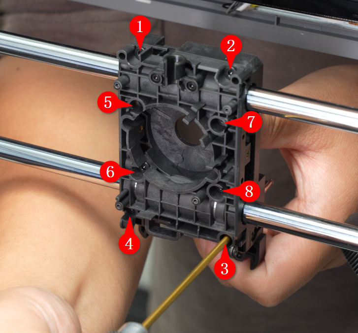
Step 3: Remove the Toolhead Carriage Assembly
Use an H2.0 hex wrench to remove the eight mounting screws. Hold both the front and rear covers of the toolhead carriage, slightly tilt the front cover first, then remove the carriage carefully to prevent the four springs at the top of the front cover from falling out.

Step 4: Remove AP Board Cover
Refer to this Wiki to remove the AP board cover from the frame:
Step 5: Remove Printer Housing
1.Remove the filament guide bracket, buffer, and rear panel:
2.Remove the AP board cover and left side panel:
3.Remove the adaptive airflow switching assembly and right side panel:
Step 6: Remove XY Belts
Use a hex wrench to push the belt clamp slightly outward, then remove the belt clamp from the belt to take the belt out. If the belt is loose, you can push the belt directly to remove the clamp without using the hex wrench.

Pull the belts on both sides of the X-axis and remove them from the two Y-axis carriages.

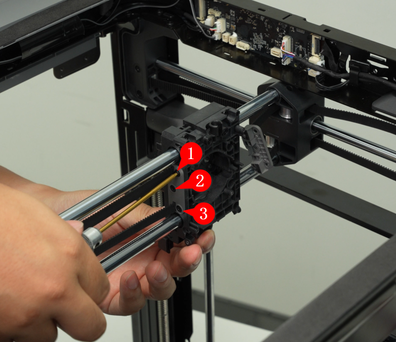
Step 7: Remove the X-Axis Assembly
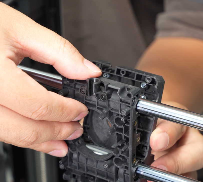
Use an H1.5 hex wrench to remove the four screws securing the outer panels of the Y carriages, and take off the panels from both the left and right Y carriages.
Rotate the X-axis assembly diagonally across the printer and remove the X-axis assembly.
Installing the X-Axis Assembly / Toolhead Carriage Assembly
Steps 1–3 apply to installing the X-axis assembly. Steps from Step 4 onward are shared for both X-axis and toolhead carriage replacement.
Step 1: Install X-Axis Assembly
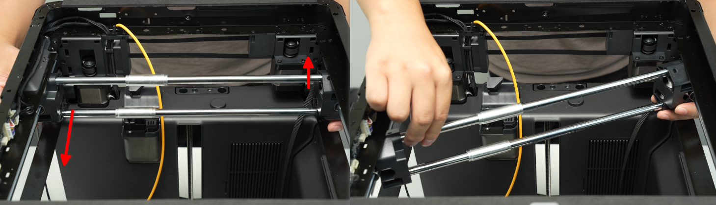
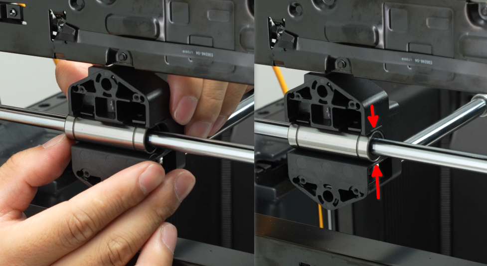
Place the X-axis assembly diagonally into the printer, align the Y carriages with the Y linear bearings, then rotate the X-axis assembly into position.
Note: After installation, check that the edges of the Y linear bearings align with the Y carriages. If they do not, push the bearings to align them. If the bearings protrude too much, remove and reinstall them.
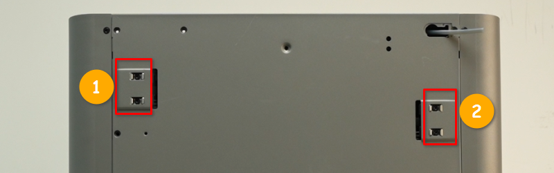
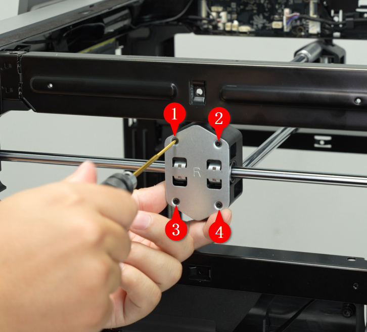
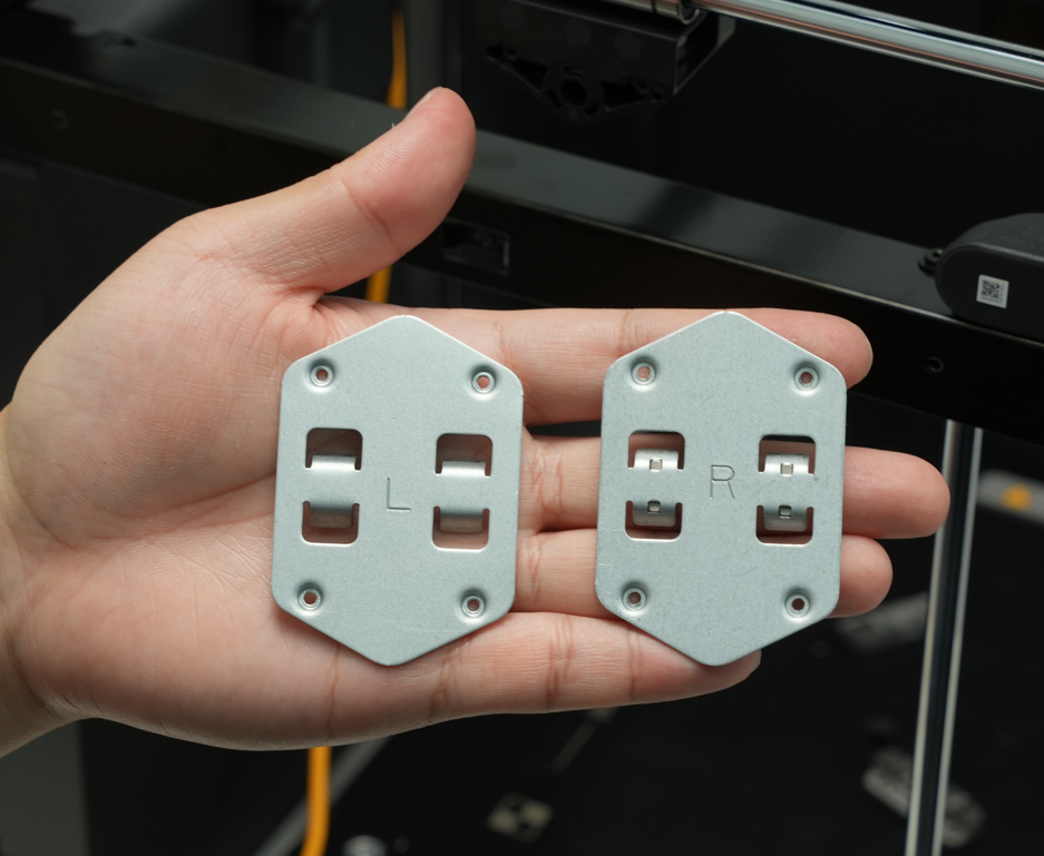
Before installing the panel, check the letter on it: Left = L, Right = R. The panel marked L goes on the left side of the printer, near the left side panel.
Install the left and right panels and use an H1.5 hex wrench to tighten the eight screws (four on each side).
Step 2: Thread the XY Belts
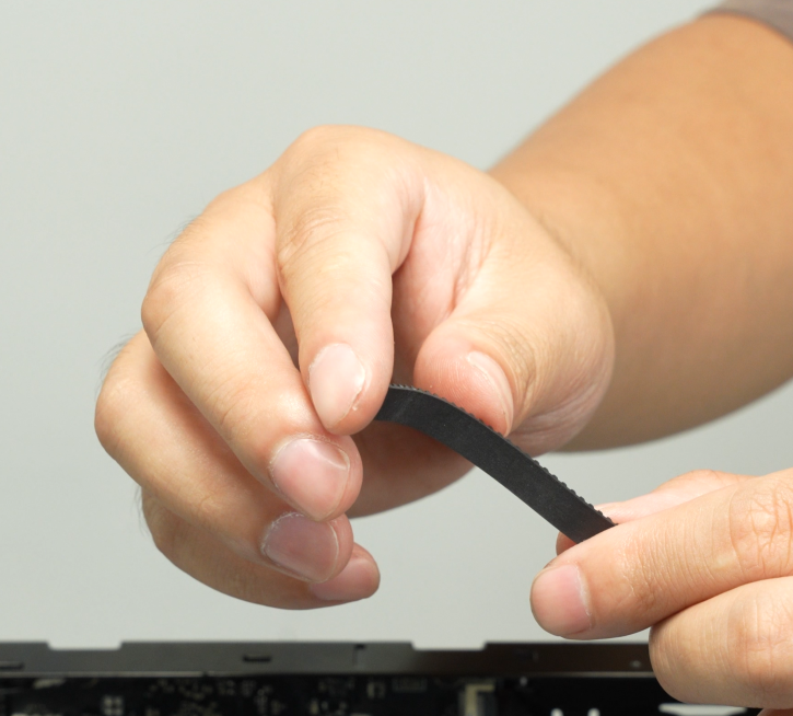
Fold the belt end to make it easier to thread through the Y carriage.
Thread the belt through the idler pulley on the Y carriage as shown in the image below.
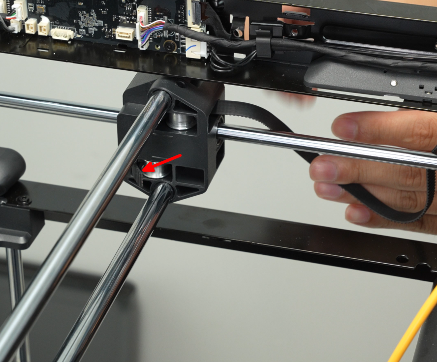
First thread the belt through the Y carriage, then through the front idler pulley, and finally through the bottom idler pulley.

Thread the belt through the belt clamp, align the teeth of the clamp with the teeth on the belt, ensuring the raised dot is at the belt’s end. Then pull the belt to snap the clamp and belt together into the belt clamp.

Install the other XY belt using the same method.
Step 3: Install Printer Housing
1.Install the right side panel and adaptive airflow switching assembly:
2.Install the left side panel and AP board cover:
3.Install the rear panel, buffer, and filament guide bracket:
Step 4: Install Toolhead Carriage Assembly
Before installation, check that the springs are on the front cover of the toolhead carriage.
Align the two aluminum sleeves on the X-axis vertically. Position the bottom of the toolhead carriage front cover against the sleeves, then slowly rotate the front cover until the top of the cover contacts the sleeves.

Next, install the toolhead carriage rear cover and use an H2.0 hex wrench to tighten the eight screws in a diagonal pattern.
Step 5: Install the Belt Clamp
First, install the right belt clamp (near the right side panel) onto the toolhead and tighten the three screws with an H2.0 hex wrench.
Push the toolhead to the rear right, then firmly install the belt clamp on the other side onto the toolhead and tighten the three screws with an H2.0 hex wrench.

Manually push the toolhead carriage back and forth along the XY directions as widely as possible 3–5 times, then tighten the four tension screws with an H2.0 hex wrench.
Step 6: Install Components on the Toolhead
1.Replacement of P2S Extruder Motor
2.Install the nozzle eddy current sensor:
The eddy sensor must be manually adjusted after all components are installed.
3.Install the drag chain mount, connect the toolhead cables and drag chain to the toolhead carriage, then install the toolhead circuit board.
4.Install the extruder assembly and cutter lever.
5.Install the hotend heater assembly, hotend fan, toolhead shell, and hotend.
Step 7: Adjust the Eddy Sensor
Refer to the following Wiki to adjust the eddy coil position:
Verifying Success
Connect the power, turn on the printer, and run the machine calibration process to confirm it completes successfully.
If any issues occur, review all replacement steps, ensure all components are installed correctly, and try again.