
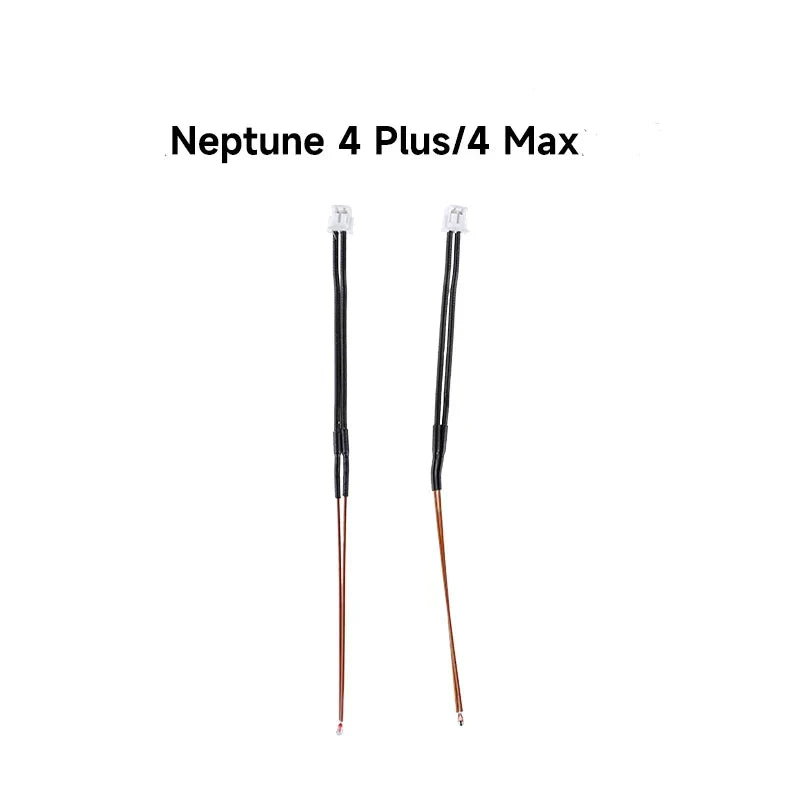


Neptune 4 Max / 4 Plus Thermistor
No se pudo cargar la disponibilidad para recoger
Utilice este texto para fomentar la comunicación o promover el intercambio en las redes sociales.
How to replace Neptune 4 Max thermistor and ceramic heating piece?
Right behind the print head, unplug the rear fan assembly port cable. Use a 2.5mm Allen wrench to loosen the four fixing screws of the “rear fan assembly ” and remove the rear fan assembly.
Use a 2.0mm hex wrench to loosen the two fixing screws of the “cable fastener”. Use a 2.0mm Allen wrench to loosen the fixing screws of the overall print head assembly.

Press the “horn terminal ”on both sides with your hands, the print head cable will pop up automatically, and then take out the print head cable.
Use a 2.0mm hex wrench to loosen the two fixing screws of the “print head front cover ”, and remove the entire print head assembly. Separate the front cover of the overall print head assembly.

Unplug the port of the “heating rod ”and “thermistor” connecting cables in the extrusion adapter board.

Remove the black “silicone sleeve ” wrapped on the heating block. Remove the heating element snap ring, do not use too much force to avoid damage to the ceramic heating element. Remove the ceramic heating element and thermistor.
Take out the new ceramic heating element and thermistor and place them in the installation position.

Install the heating element snap ring. Install the black “silicone sleeve ” wrapped on the heating block.
Insert the cable port of the thermistor into the “TH ” port of the extrusion adapter board, and insert the cable port of the heating rod into the “HE” port of the extrusion adapter board. (Make sure to arrange the cables)
Install the front cover of the overall print head assembly.
Note: There is a groove design, and slide-in installation.
Place the overall print head assembly to the installation position in front of the print head, and use a 2.0mm hex wrench to tighten the two fixing screws of the “front cover of the print head ”.
Press the “horn self-locking terminal” on both sides with your hands to open the port, and then insert the print head cable port into.(Note that the cable passes under the top profile.)
Use a 2.0mm hex wrench to tighten the two fixing screws of the “cable fastener ”.
Use a 2.0mm hex wrench to tighten the fixing screw of the overall print head assembly.
Take out the fan assembly, align it with the screw hole installation position, and use a 2.5mm hex wrench to tighten the four fixing screws of the rear fan assembly.
Insert the fan assembly port cable.
Power on the printer. Click “Prepare-Temp ” on the touch screen, and then set the nozzle temperature to 210℃ on the temperature control interface.
Press the extruder handle and load the filament into the extruder. Operate on the touch screen to enter the “Extruder ” interface, after setting the length of extrusion filament, click “Load”.
Observe that the nozzle extrudes filaments normally. After re-leveling the printer, it can be used normally.