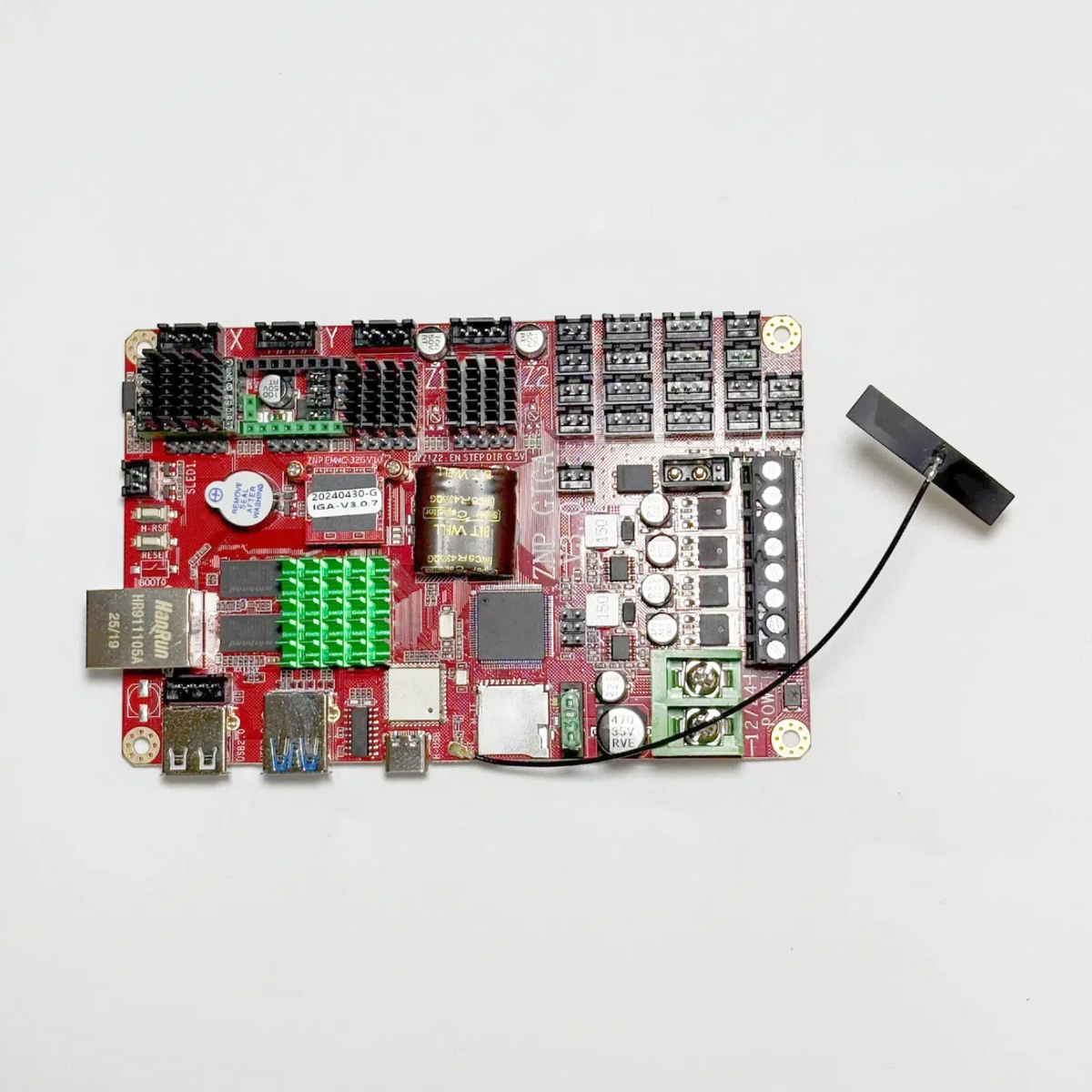


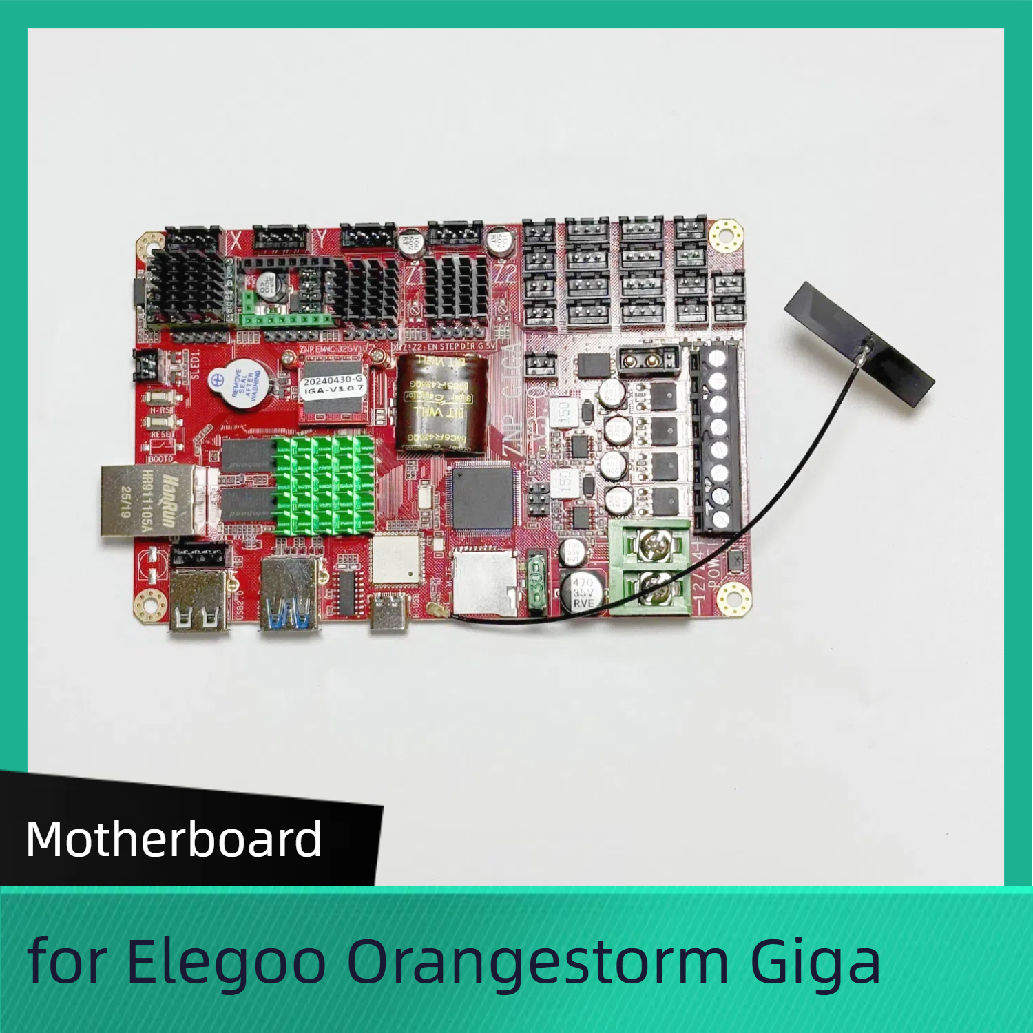


Motherboard for Elegoo Orangestorm Giga
No se pudo cargar la disponibilidad para recoger
Utilice este texto para fomentar la comunicación o promover el intercambio en las redes sociales.
Precision Power for Industrial-Grade 3D Printing
Engineered for the Elegoo Orangestorm Giga, this high-performance motherboard is the central force behind your most ambitious 3D prints. With support for ultra-fast motion control and seamless component integration, it delivers the speed, accuracy, and durability required for industrial-scale creations. Whether you’re printing prototypes, mechanical parts, or large-format models, this motherboard ensures every layer is crafted with mechanical precision and unwavering consistency. Expect less downtime and more production—this is where reliable printing begins.
Optimized for Complex Prints and Multi-Axis Control
Designed with multi-axis motion systems and high-speed G-code processing in mind, this motherboard unlocks the full capabilities of the Orangestorm Giga. It features intelligent thermal management, optimized stepper control, and advanced expansion ports that support multiple extruders, sensors, and future upgrades. Ideal for professionals and makers pushing the limits of additive manufacturing, this motherboard ensures smooth execution of complex print jobs without sacrificing speed or quality.
Built for the Long Haul – Durability Meets Innovation
Built using industrial-grade PCB materials and reinforced power regulation components, this motherboard is made to last through extended print cycles and demanding workloads. It’s designed with smart fault detection, thermal shutdown features, and stable voltage regulation to protect your investment and maintain high output performance. From the first layer to the final finish, you can rely on it to deliver unmatched reliability and resilience, even under continuous use.
for more FDM spare parts
Why Choose Lancer3D Products?
Quality Assurance: Each product in our catalog undergoes rigorous quality checks to ensure optimal performance and reliability.
Expert Support: With our dedicated customer support, you can rely on expert guidance and assistance.
Innovation at Your Fingertips: We strive to bring the latest advancements in 3D printing technology to your doorstep.
Shop with Confidence
At Lancer3D, your satisfaction is our priority. Feel confident in your purchases, knowing that you're investing in top-notch products backed by our commitment to excellence.
Explore our catalog below and revolutionize your 3D printing journey with Lancer3D.
Motherboard Replacement
When to Replace the Motherboard
If the motherboard is not functioning properly, it needs to be replaced with a new one.
Tools and Materials
A 2.0mm Allen wrench
A flathead screwdriver
A phillips screwdriver
5 cable ties
A new motherboard
Tutorial Video
Precautions and Machine Status Before Starting Operation
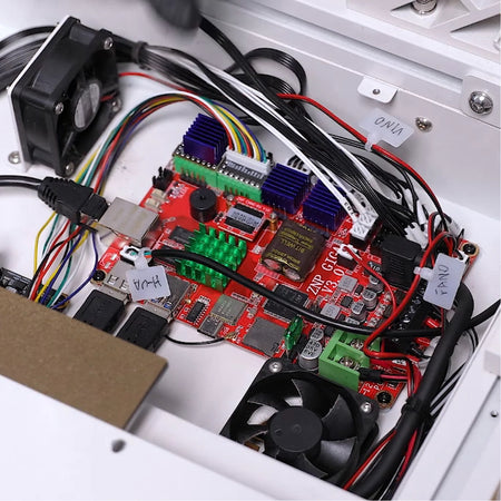
The procedure involves replacing the motherboard and managing the wiring. Before disassembly, ensure all necessary precautions are taken, turn off the machine, and disconnect the power.
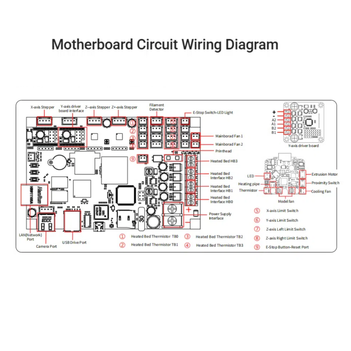
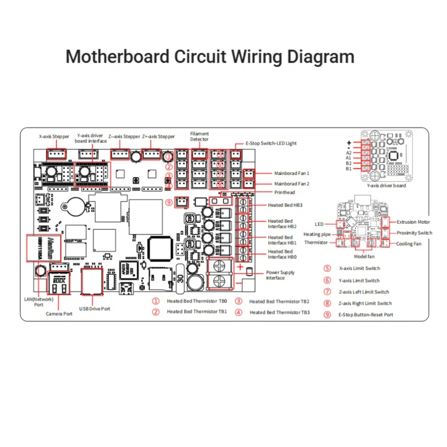
Motherboard Circuit Wiring Diagram

Instruction
1.Power off the printer and unplug the power cord.
2.Use a 2.0 mm Allen wrench to loosen the two screws securing the PEI limit block located at the front and back right sides of the printer, then remove the PEI limit block. 3.Disconnect the ribbon cables from the rear adapter board located on the right side of the printer.

4.Use a 2.0mm Allen wrench to loosen the 8 screws securing the power supply cover.

5.Slide the power supply cover downward towards the heated bed, then lift the outer edge of the cover to remove it.


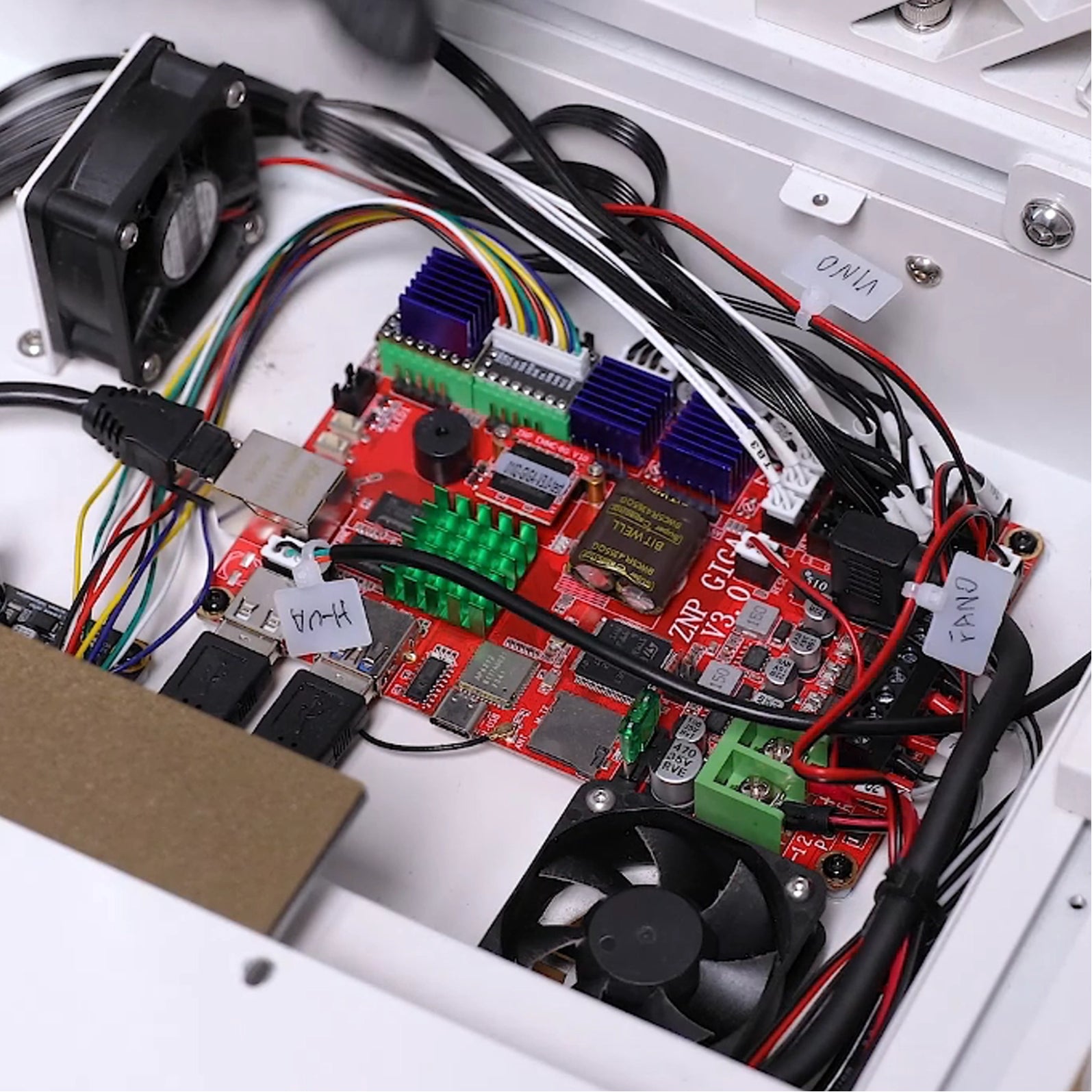
6.Use cable ties or label paper to mark the ribbon cables that lack original markings, ensuring they correspond to the port names on the motherboard.
7.Disconnect all ribbon cables from the ports on the motherboard. Use a 2.0mm Allen wrench to loosen the 4 screws securing the motherboard, and remove the old motherboard.
8.Prepare the new motherboard, align it with the screw holes, place it in the installation position, and tighten the 4 screws using a 2.0mm Allen wrench.
9.Insert each ribbon cable into the motherboard according to the port shape and label information.
Note: Follow the "red positive, black negative" principle.

10.Take out the power supply cover, and tilt the inner side towards the heated bed. Slide the cover to the installation position by aligning it with the screw holes.


11.Note: Tidy up the ribbon cables connected to the rear adapter board. Do not leave the cables under the power supply cover.
12. Use a 2.0 mm Allen wrench to tighten the 8 screws fixing the power supply cover. (Long screws are fixed at the front and back of the cover; short screws are fixed on the right side.)

13.Insert the ribbon cables into the rear adapter board on the right side of the printer according to the label information.
14.Put the PEI limit block in the installation position. Use a 2.0 mm Allen wrench to tighten the 2 screws fixing the PEI limit block, with one screw in the right front of the printer and the other at the back.

15.Plug in the power cord and power on the printer.
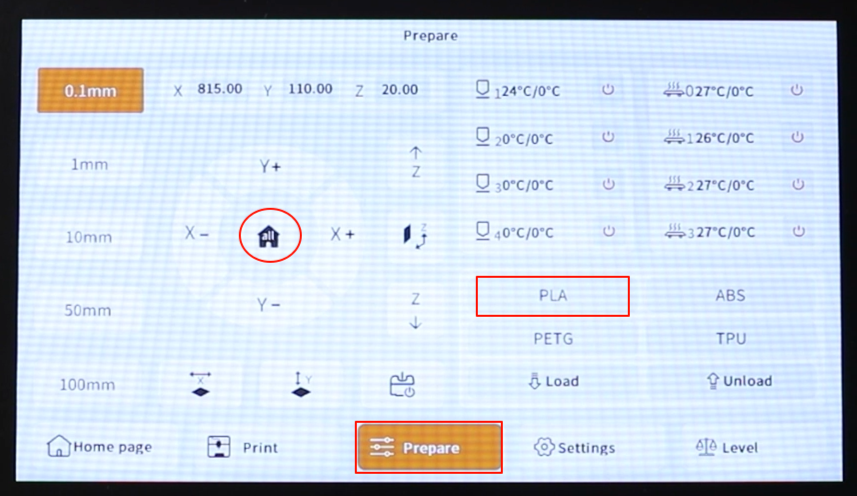
16.Touch "Prepare - all (Home icon)" on the touchscreen. The printer will returns to zero position. After the printer moves normally, touch "PLA". After the nozzle and hotbed are heated, the printer can be used normally.