


MC Board for Bambu X1 Series
No se pudo cargar la disponibilidad para recoger
Utilice este texto para fomentar la comunicación o promover el intercambio en las redes sociales.
Compatibility – MC board is fully compatible with X1 series, serving as the direct replacement for the original main control board.
Central Control Hub – Acts as the core controller to manage XYZ-axis motors, cooling fans, heat bed and AMS for coordinated printer operation.
Stable Performance – Built with premium electronic components for reliable signal transmission and stable long-hour printing performance.
Easy Installation – Features standard interfaces and reserved mounting points for plug-and-play setup without complex wiring or modification.
Precision Printing Support – Ensures accurate motion control and thermal regulation, supporting high-precision printing and consistent output quality.
MC board is the abbreviation of the machine controller board. It is the control center for the XYZ-axis motors, the cooling fans, the heat bed, and the AMS.
In the Box
- MC Board*1
Compatibility
X1 Series Exclusive
Replacing the MC board
This guide provides detailed steps for replacing the MC board in X1 series printers.
What it is
MC stands for Machine Controller, Which is the unit that controls all the moving parts of the printer.

When to use this guide
The board would need to be replaced in case of a failure where the machine would fail to function mechanically in cases of physical damage or board burnout. In some cases the log file would be needed to determine if any issue with the machine originates from the MC board
Tools and materials needed
New MC board
H1.5 & H2.0 Allen key
Tweezers
Hair Dryer
Silicon glue
Safety warning and Machine state before starting operation
Prior to commencing with the process in this guide, please make sure the machine is switched off and that the AMS along with the PTFE tube and filament buffer are removed
Operation guide
Step 1 - (Disassembly) Remove screws
Undo the screws at the back of the printer as marked below. There are a total of 14 screws to undo, 10 of them in the first image and 4 in the second image as shown below.

Step 2 - Removing the rear cover
To remove the rear cover, it is important to first pull the left side so that the left belt tension port doesn't get in the way, followed by the right side. Push the PTFE tube outlet inwards to free it from the cover.

Step 3 - Removing the excess chute
Undo the screws located at each side of the excess chute. once done, take out the excess chute. Some printers have three screws to secure the excess chute, while some only have two; please refer to your unique situation.
Note: For some versions, the heat bed cables are fixed to the bottom of the excess chute with a buckle, do not use too much force when taking off the excess chute.
Two screws case:


Step 4 - Disconnecting cables
NOTE: Prior to proceeding with this step, it is recommended to mark all cables and take photos in order to remember their location when reattaching them to the new MC board.
Disconnect all cables from the MC board.
A hair dryer should be used to gently heat and soften the silicone adhesive surrounding any connectors, such as the heatbed wire, to facilitate their removal.

Step 5 - Removing the MC board
Undo the 4 screws holding the MC board in place, and then remove the board itself.
Note: The bottom right-hand corner screw also holds the “ground” connector to it

Step 6 - (Assembly) Installing the MC board
Place the new MC Board in the same location and orientation as the previous one and use the 4 screws Install the MC board. Remember to attach the “ground” cable to the bottom right-hand side screw

Step 7 - Connecting the cables
Connect all the cables to the MC board referencing the photos or marking you have done in the disassembly stage. On the heat bed cable, place a dab of silicone glue to secure it in and wait 30 minutes for the glue to completely dry.


Step 8 - Installing the excess chute
Install the excess chute by sliding it back in its position, pay attention to the protruding tabs on both sides of the chute. Finally, secure it in place with 2 screws at each side of the top of the chute.

Step 9 - Installing the rear cover
First, pass through the tube bracket and then secure the right side of the back cover past the right belt tensioner as shown below, followed by the left belt tensioner.

Step 10 - Lock screws
Screw the back panel back on. Take note of the different types of screws (10 and 4) used as pointed out previously

How to verify completion/success
Check the indicator lights on the control board
Normal State: the MC board flashes red once every 5 seconds
Before tightening all screws, you may temporarily install or leave the cover off (be cautious of electrical safety and operate with the power disconnected). Then power on to check whether the indicator lights are functioning normally. If the lights are normal, fasten the screws to avoid rework.
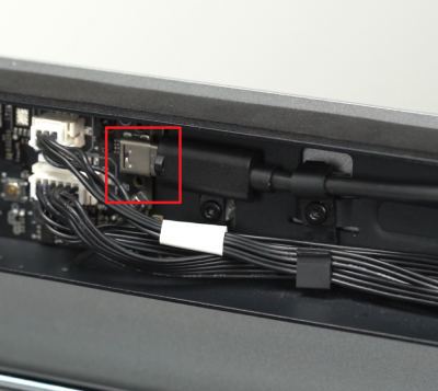
If the indicator light on the MC board is not flashing once every 5 seconds (for example, once every 30 seconds), please check whether the USB-C cable is connected correctly.
Note: The letter "A" and the bump should face outward.
Connect the power cable and verify.
Connect the power cord and turn on the power.
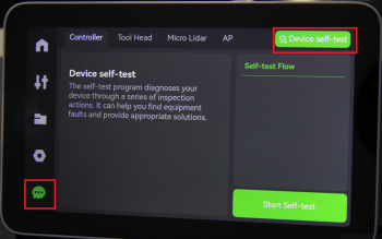
For X1 and X1-C (without AMS), Run a Device self-test operation as shown below and if no errors occur, the replacement was successful.
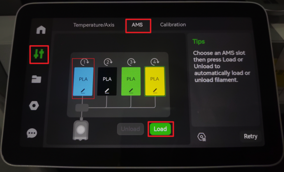
For X1-C combo (with AMS), you also need to install the AMS buffer, connect the AMS and run the filament loading procedure on the display menu. if no errors occur, the replacement was successful.
Should you come across any issues, first retrace your steps and check all connections to try again. If problems persist, contact the service team for further assistance.