


MC Board for Bambu - H2 Series
No se pudo cargar la disponibilidad para recoger
Utilice este texto para fomentar la comunicación o promover el intercambio en las redes sociales.
H2D/H2C MC board
The MC Board, installed in the printer's electronics section, governs precise movements and control over the printer's operation.
Precise signal transmission: This MC board manages communication between the printer control system and connected modules, ensuring stable data flow for consistent printing performance.
Durable circuit construction: Built with reinforced circuit traces and quality components to withstand repeated thermal cycling and extended operation hours.
Direct fit replacement: Designed as a direct replacement for the original MC board, matching the exact mounting hole positions and connector layout for hassle-free installation.
Overload protection: Features integrated overcurrent protection to prevent damage to the main control system during unexpected electrical fluctuations.
Wide compatibility: Engineered to work with H2D/H2C printer systems, providing a versatile solution for different printer configurations.

In the Box
- MC Board*1
- BT2-5 Screw*6
Compatibility
H2 Series
Replace H2D/H2C MC board
This article introduces how to replace H2D and H2C MC board
Note: This page uses the H2D machine as an example. The replacement steps are exactly the same for the H2C.

The spare parts for the MC board include the following:
MC board * 1
ScrewsBT2x5 *6 - for securing the MC board *6
When to replace
Under normal power supply conditions, the MC board's indicator light does not flash;
The connector is damaged, showing obvious component failure;
The Bambu Lab customer support confirmed through the log files that it is an issue related to the MC board.
Tools and materials needed
1.New MC board
2.H2.0 Allen key
3.H1.5 Allen key]
Safety Warning
IMPORTANT!
It's crucial to power off the printer before conducting any maintenance work, including work on the printer's electronics and tool head wires. Performing tasks with the printer on can result in a short circuit, leading to electronic damage and safety hazards.
During maintenance or troubleshooting, you may need to disassemble parts, including the hotend. This exposes wires and electrical components that could short circuit if they contact each other, other metal, or electronic components while the printer is still on. This can result in damage to the printer's electronics and additional issues.
Therefore, it's crucial to turn off the printer and disconnect it from the power source before conducting any maintenance. This prevents short circuits or damage to the printer's electronics, ensuring safe and effective maintenance.
Remove the MC board
Step 1: Remove the rear panel
Step 2: Remove the purge chute
Step 3: Remove the MC board
1.Remove the bundle of cables from the cable clip to provide space for the subsequent plug removal.

2.Disconnect all connectors on the front of the MC board. Please note that some plugs use a locking mechanism, and you must unlock the latch before pulling them out. For specific plugs that require unlocking, refer to the component correspondence table in the installation steps.

Additionally, to prevent the plugs from loosening during transportation, the three stepper motor plugs beneath the heatsink are reinforced with electronic silicone. To remove these three plugs, you first need to use a sharp tool, such as tweezers, to make a cut in the silicone around the plug before pulling it out.
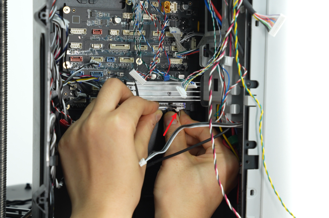
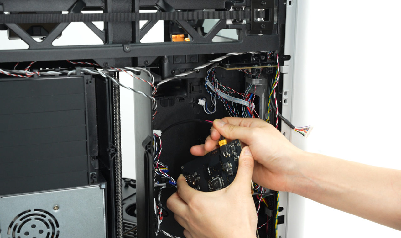
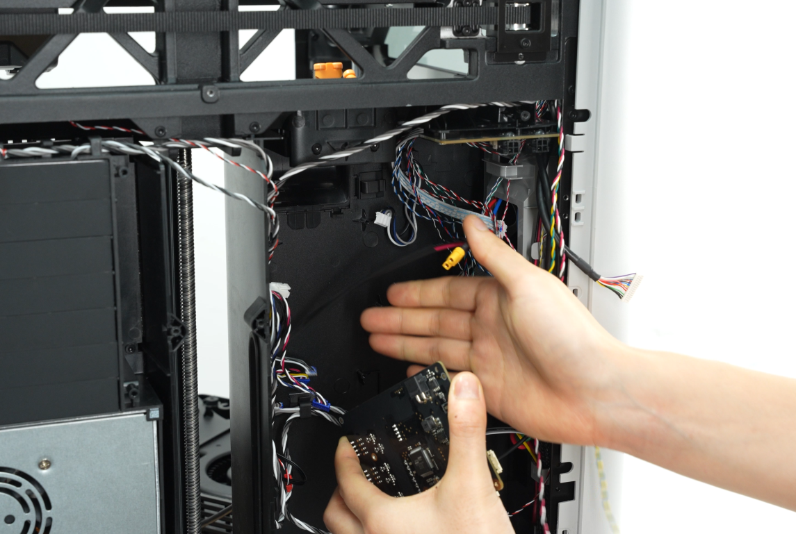
3.Use an H1.5 Allen key to remove the 6 fixing screws and take the MC board out of the lining. Please note that there is also a power input plug for the MC board on the back; do not pull it forcefully.
4.Disconnect the power plug from the back of the MC board.
Install the MC board
Step 1: Install the MC Board
1.Insert the power plug into the back of the MC board.

2.Align the new MC board with the small holes in the lining, then use an H1.5 Allen key to tighten the five screws.
Please ensure that before tightening the screws, you check that there are no plugs being pressed against the MC board from above, below, or on the sides to avoid the need for rework.

3.Refer to the diagram below to sequentially reconnect the cables to the MC board and organize the cables.


4.Recheck the above table again to see if there are any missing plugs. If there are any omissions, please make sure to insert them back.

Note: The non-laser version (without a built-in air pump) H2D has 5 available sockets, while the laser version (with a built-in air pump) has 4 available sockets.
Non-laser version H2D as an example:
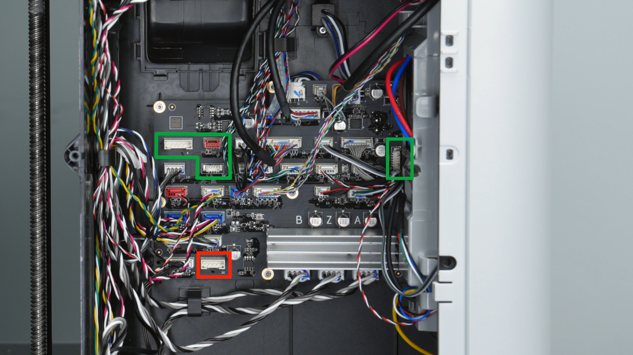
For H2C, it is required to replug the cable of Vortek communication into No.8 socket.

The Z motor is mounted on the base, while the A and B motors are located on the XY plane. If you are unsure about the plugs for the A, B, and Z motors, you can gently pull on the cables to see which motor's cable moves. For example, if you pull a certain plug and the cable connected to the A motor moves, it indicates that this motor is the A motor. The identification method for the B and Z motors is similar.
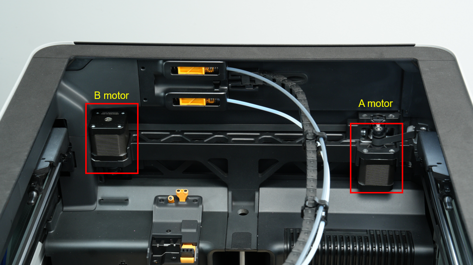
Friendly Reminder: This is just a recommended wiring method, as it provides a more aesthetically pleasing appearance. If you prefer not to wire it this way after replacing the MC board, just ensure that the plug connections are stable, and functionality will not be affected.

Step 2: Install the Purge Chute
Step 3: Install the Rear Panel
Step 4: High-temperature Bed Leveling
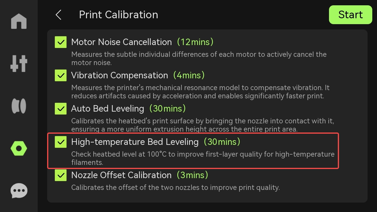
After replacing the MC board, to prevent any abnormal printer operation, it is necessary to perform a high-temperature bed leveling. Please tap on the screen "Settings" > "Calibration" > "Print Calibration", check "High-temperature Bed Leveling", and start the calibration process.
To verify completion/success
Check the indicator lights on the control board
Normal State: The MC board indicator light stays on (top left), flashes slowly (bottom left), and flashes rapidly (right).
Before tightening all screws, you may temporarily install or leave the cover off (be cautious of electrical safety and operate with the power disconnected). Then power on to check whether the indicator lights are functioning normally. If the lights are normal, fasten the screws to avoid rework.
Connect the power cable and verify.
Connect the printer power, turn on the printer, and operate from the screen to run the device self-test process. If the self-test passes, it indicates that the operation was successful.
If not, please check all connections again and try again.
H2S MC board
Wide compatibility: Engineered to work with H2S printer systems, providing a versatile solution for different printer configurations.
In the Box
- MC Board*1
- BT2-5 Screw*6
Compatibility
H2 Series