


Hotend Heating Assembly - H2S for Bambu Lab
No se pudo cargar la disponibilidad para recoger
Utilice este texto para fomentar la comunicación o promover el intercambio en las redes sociales.
The Hotend Heating Assembly heats the hotend and uses a clamping mechanism to secure it, enabling quick removal for maintenance or replacement.
Installation
Please learn about the installation on Bambu Lab Wiki.
In the Box
Hotend Heating Assembly*1
M3-10 Screw*3
Thermal Insulation Foam*1
Compatibility
H2S and H2S Laser
Replace H2S Hotend Heating Assembly
In this guide, we will explain how to replace the H2S hotend heating assembly.
¶When to Use
This guide is used when there is a problem with the hotend heating assembly.
Common issues that require replacing the H2S hotend heating assembly include:
The hotend heating assembly is wrapped in plastic due to printing failures
Damaged heater or thermistor
Damaged hotend metal clips
Recommended by Bambu Lab technical support
Required Tools and Materials
New hotend heating assembly
H1.5/H2.0 Allen key
Flat-head tweezers
25 minutes
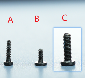
Screw List
Screw A: 3 screws in total (shared with the rear cover) for the back of the part cooling fan and the toolhead rear cover: BT2x6.5
Screw B: 2 screws in total for the left and right sides of the part cooling fan: BT2x5
Screw C: 3 screws in total for the hotend heating assembly: M3*10
Safety Warning
IMPORTANT!
Always turn off the printer's power before performing any maintenance work, including maintenance on the printer's electronic components and toolhead wires. Performing such operations while the printer is powered on may cause a short circuit, resulting in damage to electronic equipment and safety hazards.
During maintenance or troubleshooting, you may need to disassemble components such as the hotend, exposing wires and electronic components. If they come into contact with each other or with other metal or electronic components while the printer is still powered on, a short circuit may occur. This will damage the printer's electronic components and cause other problems.
Therefore, be sure to turn off the printer and disconnect the power supply before performing any maintenance to prevent short circuits or damage to the printer's electronic components, ensuring that maintenance work is carried out safely and effectively. If you have any questions about this guide, please click here to submit a ticket, and we will reply promptly and provide assistance.
Removing the Hotend Heating Assembly
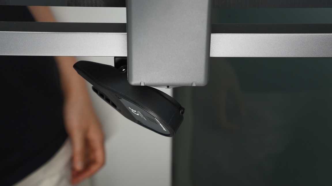
Step 1: Loosen the Part Cooling Fan
Unscrew the 3 screws of the part cooling fan, among which the 1 screw on the back is shared with the toolhead rear cover.
After loosening the screws, the fan will hang naturally. Do not pull the fan to avoid damaging the connector!
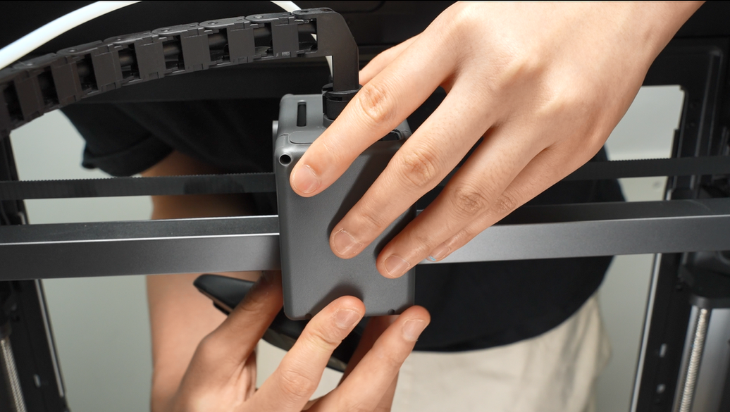
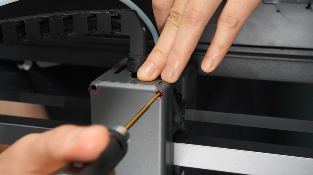
Step 2: Loosen the Toolhead Rear Cover
Remove the 2 screws on the top of the toolhead rear cover and open the module interface cover;

After opening the interface cover, you can insert your fingers and gently push the toolhead rear cover backward from the inner wall.

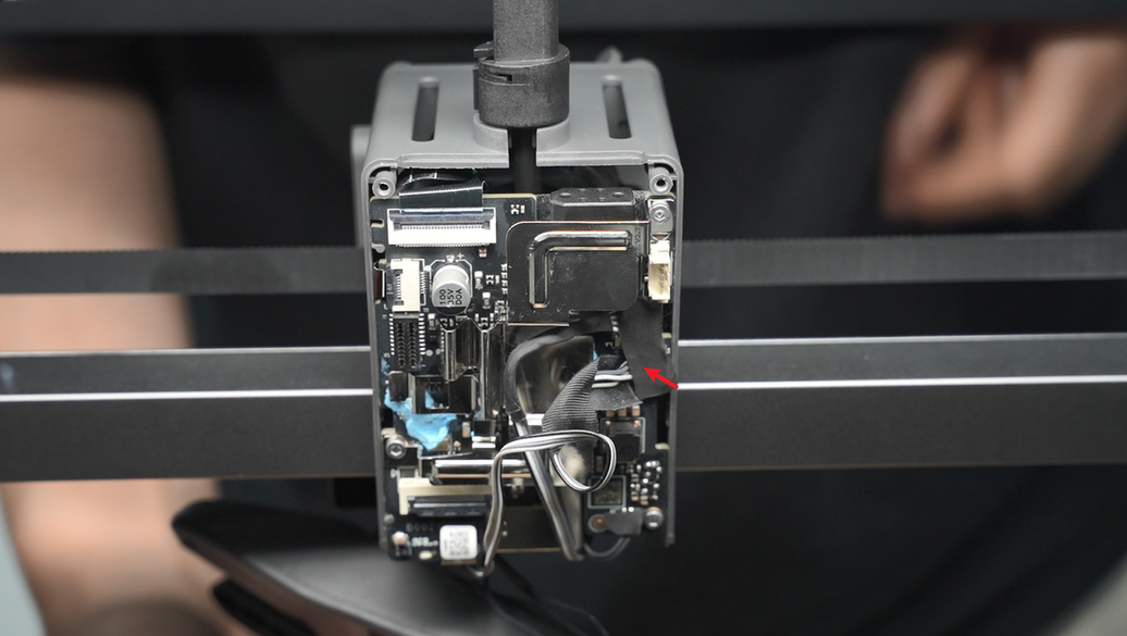
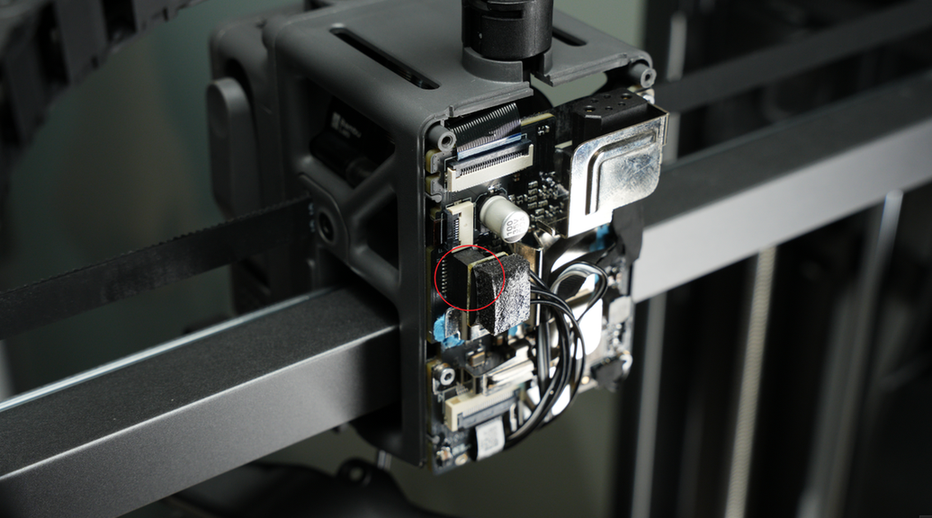
Step 3: Disconnect the Connector on the TH Board
Disconnect the hotend heating assembly plug;
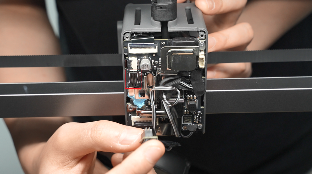
Tear off the acetate tape on the part cooling fan plug;
Please keep the tape as you will need to reattach it during installation.

Pinch the root of the connector and apply force in the direction perpendicular to the PCB board to disconnect the part cooling fan plug.
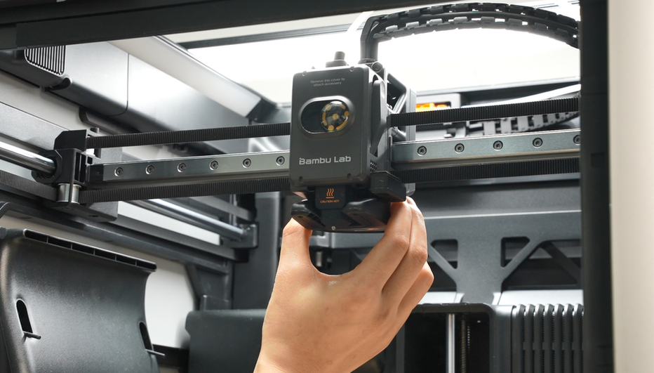
Step 4: Remove the Hotend
Refer to this tutorial to remove the hotend.
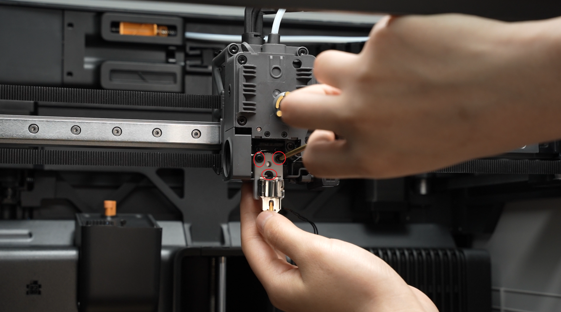
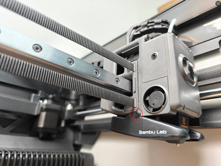
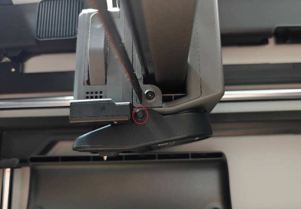
Step 5: Remove the Hotend Heating Assembly
Take out the part cooling fan cable and hotend heating cable from the cable management slot;

Remove the 3 screws of the hotend heating assembly, and take off the hotend heating assembly and the gray heat shield;

Installing the Hotend Heating Assembly
¶Step 1: Install the New Hotend Heating Assembly
Install the heat shield (very important, do not omit it), align with the screw holes and the middle positioning point, and reinstall the hotend heating assembly;

Tighten the 3 fixing screws;
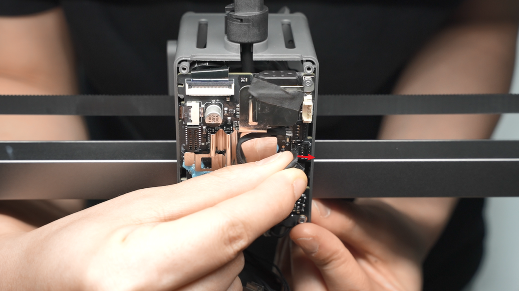
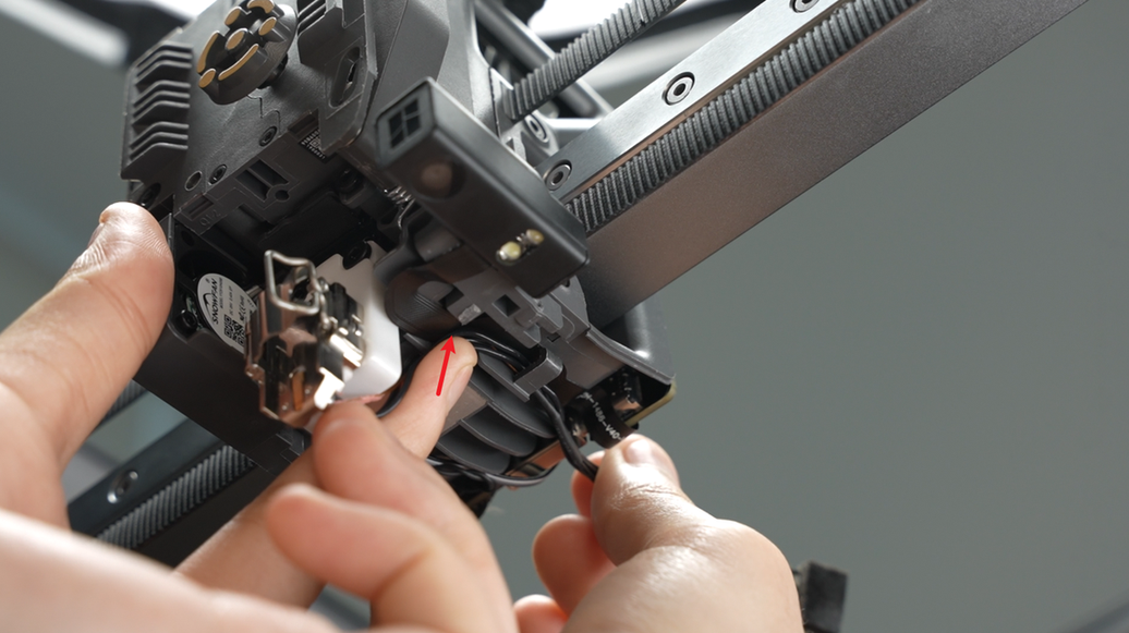
Clip the new hotend heating assembly cable into the cable management slot. After clipping in the cable, press the area indicated by the arrow as shown in the video.
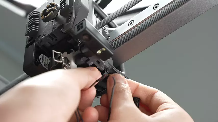
Insert the part cooling fan cable into the cable clip;

Step 2: Install the Hotend
Refer to this tutorial to install the hotend.
Step 3: Connect the Connector on the TH Board
Connect the fan cable, with the jack of the plug facing the socket on the TH board (the metal solder points of the plug face the back of the chassis), align and press down the plug;

Reattach the acetate tape;
Pre-align the screw holes of the fan, arrange the fan cable on the TH board, pull it upward, and fold the excess cable to avoid it being crushed by the fan housing or toolhead rear cover, which may cause fan malfunction.

 After arranging the cables, insert the hotend heating assembly plug, and use the hotend heating assembly plug and cable to press the part cooling fan cable.

When inserting the hotend heating assembly, ensure it is aligned with the holes and not misaligned.
Step 4: Install the Toolhead Rear Cover
Install the toolhead rear cover;
After installation, check that the part cooling fan cable is in the dedicated notch to avoid being squeezed by the rear cover frame;
 Lock in the 2 rear cover fixing screws.
Step 5: Install the Part Cooling Fan
Align with the screw holes and install the part cooling fan; when clamping the fan, be careful not to press the fan cable.
If the cable is too long, return to step 1 of the installation guide to fold the excess cable first.
Lock in 3 screws to secure the part cooling fan.
Function Confirmation
To ensure everything is working properly, set the hotend temperature to 100°C. If the
setting is successful, the corresponding temperature will be displayed on the screen.
Equipment Calibration
It is recommended to perform a full calibration of the printer after this operation.
Potential Issues and Solutions
If you encounter problems during the installation of the new hotend heating assembly, please check the following potential issues and solutions:
Hotend Temperature is 0°C
Check the hotend heating assembly connector to ensure it is properly inserted.
Please refer to Step 5 Connect Cables.
The connector pins must be carefully aligned with the TH board.
If the problem persists, the thermistor wire may be damaged (white wire).
Hotend Cannot Heat
Check the hotend heating assembly connector to ensure it is properly inserted.
Please refer to Step 5 Connect Cables.
The connector pins must be carefully aligned with the TH board.
If the problem persists, the heater wire may be damaged (translucent wire).
First Layer Issues
Ensure the screws of the hotend heater assembly are tightened and that the heatbed leveling function is enabled before starting printing.