


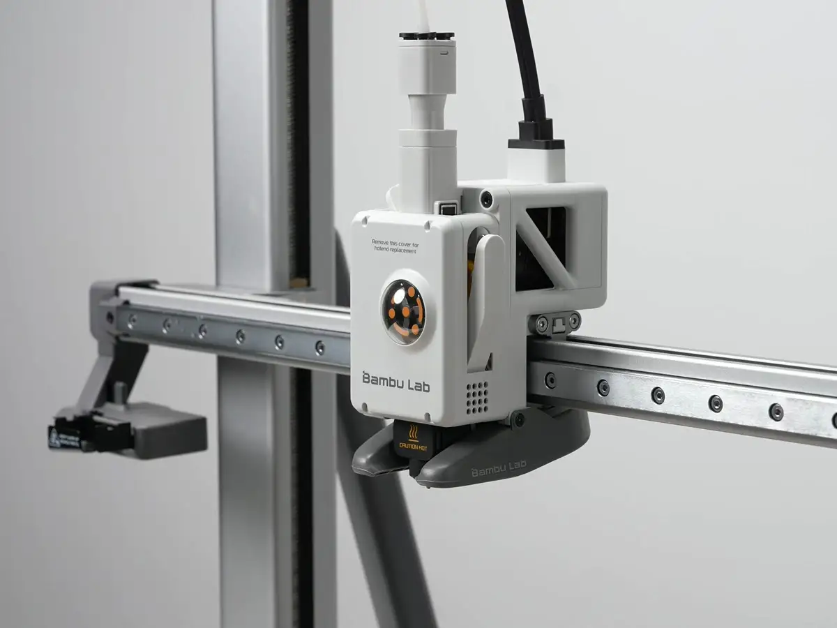
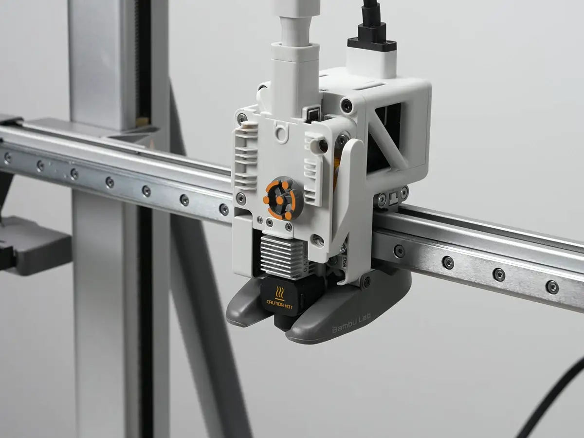
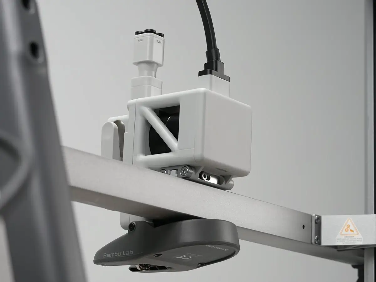
Hotend Heating Assembly for Bambu A2L
No se pudo cargar la disponibilidad para recoger
Utilice este texto para fomentar la comunicación o promover el intercambio en las redes sociales.
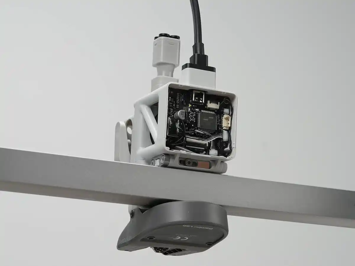
The Hotend Heating Assembly is specially designed to support the quick swap design of the hotend. A quick clamping mechanism is used to secure the heater block and heating base, enabling easy separation of the thermal and electronic components of the hotend.
In the Box
- Hotend Heating Assembly *1
- M3x10 Screw *3
Compatibility
A2L
Hotend Heating Assembly Replacement Guide for the A2L
In this wiki, you will learn how to replace the hotend heating assembly on the A2L.
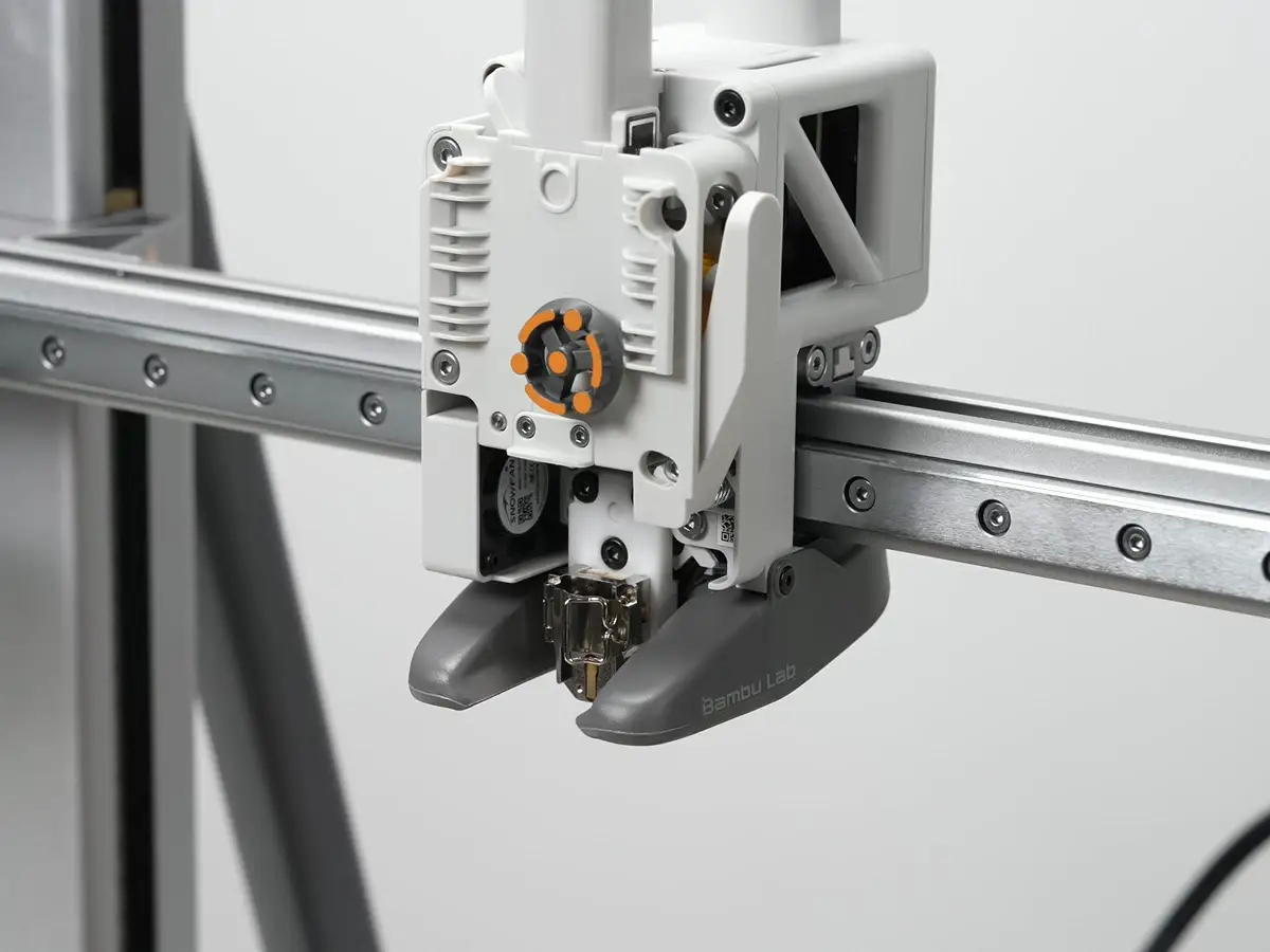
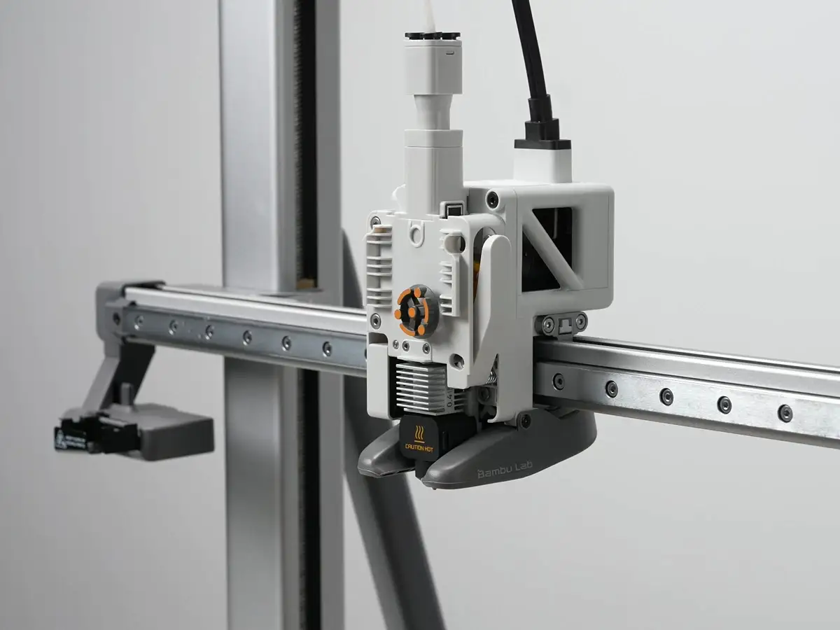
Hotend Heating Assembly

When to Replace
The hotend heating assembly composite screw thread is stripped.
There is poor first layer print quality.
The hotend temperature control is malfunctioning.
Replacement recommended by Bambu Lab technical support.
Required Tools and Materials
Hotend heating assembly.
H2.0 hex screwdriver.
Tweezers (optional).
Safety Warning
⚠️ IMPORTANT!
It's crucial to power off the printer before conducting any maintenance work, including work on the printer's electronics and tool head wires. Performing tasks with the printer on can result in a short circuit, leading to electronic damage and safety hazards.
During maintenance or troubleshooting, you may need to disassemble parts, including the hotend. This exposes wires and electrical components that could short circuit if they contact each other, other metal, or electronic components while the printer is still on. This can result in damage to the printer's electronics and additional issues.
Therefore, it's crucial to turn off the printer and disconnect it from the power source before conducting any maintenance. This prevents short circuits or damage to the printer's electronics, ensuring safe and effective maintenance. For any concerns or questions about following this guide, we recommend submitting a technical ticket regarding your issue and we will do our best to respond promptly and provide the assistance you need.
Remove the Hotend Heating Assembly
Step 1. Remove the Toolhead Front Cover
Hold the lower part of the toolhead front cover, avoiding the hotend cooling fan area, and lift upward to remove the toolhead front cover.
Step 2. Remove the Silicone Sock From the Hotend
Hold both sides of the silicone sock by the high-temperature mark, firmly pull down and diagonally to remove the sock.
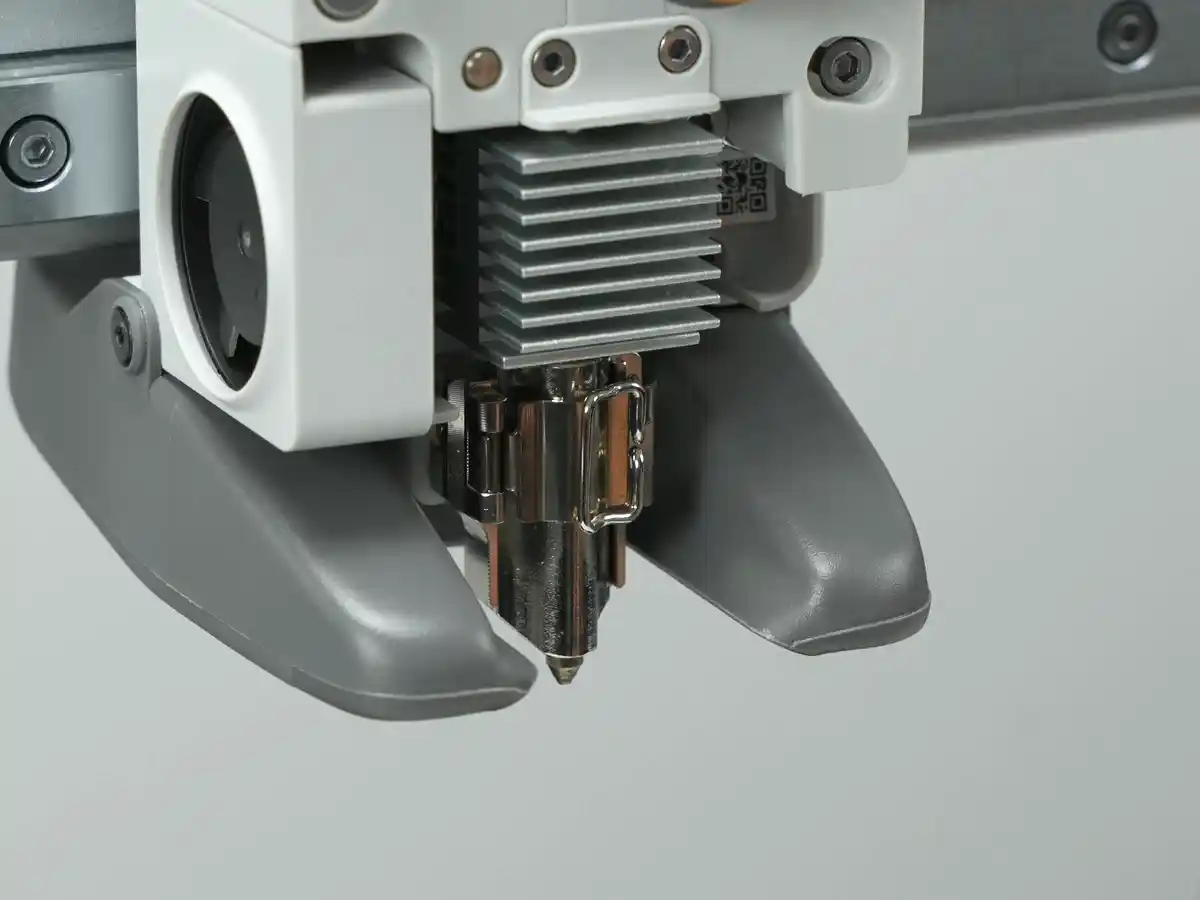
Step 3. Remove the Hotend
Ensure the hotend has cooled to room temperature and the filament has been cut; if not cut, press the filament cutter to cut the filament.Unlock the hotend locking tab, hold the heatsink at the top and bottom, and remove the hotend.

Step 4. Remove the Toolhead Rear Cover
Use your hand or the end of a pair of tweezers to hook into the groove at the bottom of the toolhead rear cover, then apply upward force to remove it.
5.Step 5. Move the Extruder Unit
Use an H2.0 hex screwdriver to remove the four screws shown, then pull the extruder forward about 5 - 8 mm to create space for disconnecting the hotend heating assembly cables.
Note:
Do not forcibly pull the extruder to avoid damaging the cables behind it.
Step 6. Remove the Toolhead Right-Side Wire Cover**
Push the toolhead right-side wire cover backward as shown, then unplug the hotend heating assembly connector.

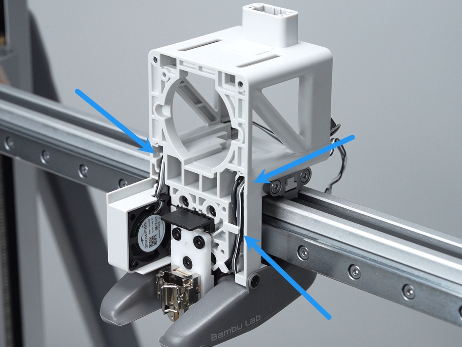
Step 7. Remove the Hotend Heating Assembl
Use an H2.0 hex screwdriver to remove the three screws indicated, then take out the hotend heating assembly

Install the Hotend Heating Assembly
Step 1. Install the Hotend Heating Assembly**
Align the hotend heating assembly into the installation position, secure it with the three screws using an H2.0 hex screwdriver, and organize the cables.

Step 2. Install the Extruder Unit
Ensure the cables on both sides are securely seated in the wire slots to prevent pinching during the extruder installation.
Push the extruder back to its original position and secure it with four screws using an H2.0 hex screwdriver.
 Step 3. Install the Toolhead Right-Side Wire Cover**
Push the right-side wire cover into the toolhead and plug in the hotend heating assembly connector.
 Step 4. Install the Toolhead Rear Cover
Align the locking tabs on the top of the toolhead rear cover, then close them. Press the lower-left and right edges of the rear cover to ensure they are securely engaged.
 Step 5. Install the Hotend
Ensure the hotend locking tab is fully open, then install the hotend onto the hotend heating assembly.
 Note:
Note:
The sequence of locking the hotend locking tab must match the demonstration exactly.
Step 6: Install the Silicone Sock
Slide the silicone sock onto the hotend from the bottom up. Ensure it is seated smoothly and does not make contact with any surrounding plastic components.
 Step 7. Install the Toolhead Front Cover
Align the top locking tabs of the toolhead front cover, then gently press downward.You will hear a "click" when installation is secure.
Verifying Success
✅ To ensure everything is normal, turn on the printer, set the hotend temperature to 200°C, and if the hotend heats normally and maintains a stable temperature, the installation is successful. After testing, set the hotend temperature back to 0°C.
Calibrate the 3D printer After Replacement
It is recommended to perform a complete calibration after replacing the hotend heating assembly to ensure smooth printer operation.