


X/Z/Y Belt for Bambu A1
No se pudo cargar la disponibilidad para recoger
Utilice este texto para fomentar la comunicación o promover el intercambio en las redes sociales.
The X Belt is a crucial transmission component within the X-Axis assembly, facilitating the connection between the X motor and the tool head, enabling smooth movement along the X-axis. It is imperative to replace the X belt promptly in cases of severe wear or breakage to avoid operational disruptions of the printer.
Compatibility
A1 Exclusive
In the Box
X Belt - A1 *1

Z Belt
Used to drive the Z-axis lead screws for vertical movement of the X-axis, ensuring the consistency in elevation.
Compatibility
A1 Exclusive
In the Box
Z Belt - A1 *1

Y Belt
The Y Belt is a crucial transmission component within the Y-axis assembly, facilitating the connection between the Y motor and the heatbed, enabling smooth movement along the Y-direction. It is imperative to replace the Y-Axis Belt promptly in cases of severe wear or breakage to avoid disrupting printer operations.
Compatibility
A1 Exclusive
In the Box
Y Belt - A1 *1

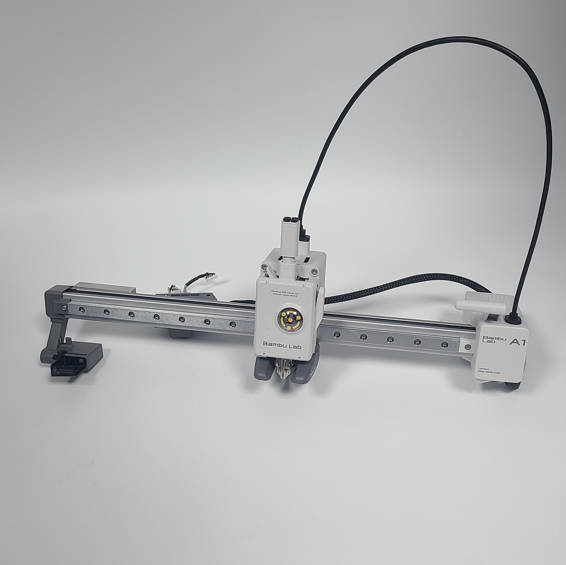
A1 X-axis Assembly Installation Tutorial
This article provides guidelines and notes related to the disassembly and assembly of the A1 X-axis, but the toolhead is not included.
A1 X-axis Installation Tutorial (Excluding toolhead)
This article provides guidelines and notes related to the disassembly and assembly of the A1 X-axis, but the toolhead is not included.
Safety Warning
IMPORTANT!
It's crucial to power off the printer before performing any maintenance work on the printer and its electronics, including tool head wires, because leaving the printer on while conducting such tasks can cause a short circuit, which can lead to additional electronic damage and safety hazards.
When you perform maintenane or troubleshooting on the printer, you may be required to disassemble some parts, including the hotend. This process can expose wires and electrical components that could potentially short circuit if they come into contact with each other or with other metal or electronic components while the printer is still on. This can damage the electronics of the printer and cause further damage.
Therefore, it's essential to switch off the printer and disconnect it from the power source before doing any maintenance work. This will prevent any short circuits or damage to the printer's electronics. By doing so, you can avoid potential damage to the printer's electronic components and ensure that the maintenance work is performed safely and effectively.
If you have any concerns or questions about following this guide, open a new ticket in our Support Page and we will do our best to respond promptly and provide you with the assistance you need.
Remove X-axis Assembly
Step 1: Disconnect the cables
Left side down the printer to expose the cable box on the bottom, and disconnect the camera cable, X motor cable, and Z motor cable in sequence.
Loosen a silver screw and slide the cable box to disconnect the USB cable, then open the Z-motor cable cover and remove the Z-motor cable from the box.

Step 2: Remove the X-axis Assembly
Remove the 6 screws located at the back of the X-axis and detach the X-axis assembly from the printer frame.

Disassemble X-axis Assembly
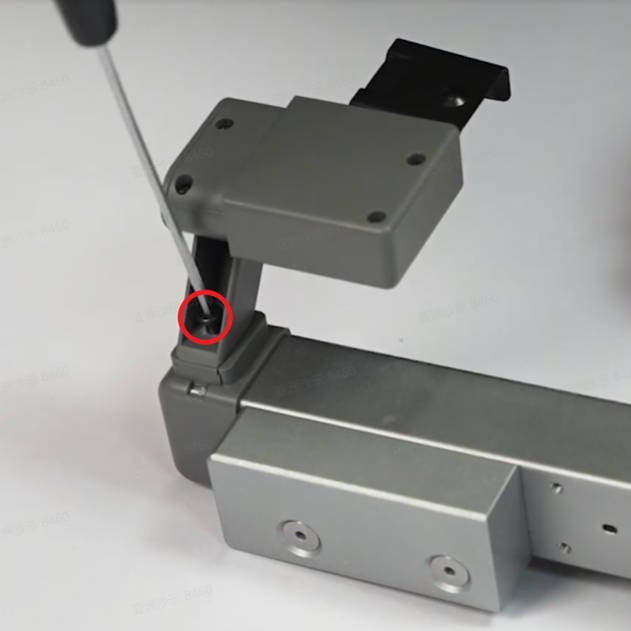
Step 1: Remove the Purge Wiper
Remove 1 screw with an H2.0 Allen key, and slide out the Purge Wiper.
Step 2: Remove the X Belt
Fix the X-axis slider with tape to prevent the slider from falling off;
Remove 1 screw with an H2.0 hex key and then remove the X-axis cover; Note: The cover screw is shorter than the purge wiper screw. Please distinguish the two screws to avoid errors during subsequent installation.
Remove the pressing block on the right side of the X Belt, hold the tensioning block, and pull out the X belt from the left side;

Step 3: Remove the X-axis Pulley and the weight block
Remove the idler shaft with an H2.0 hex key, take out the X-axis Pulley, and the 2 washers
Remove 2 screws and the weight block.

Step 4: Remove the cable management box
Remove 1 silver screw with an H2.0 hex key, and 1 black screw with an H1.5 hex key;
Open the covers and remove all the cables from the management box

Step 5: Remove the Live View Camera
Remove the front cover of the X Motor Cover;
Unlock the Live View Camera, and disconnect the camera cable, remove the Live View Camera;
Use a hex key to pry out the cable clip, and remove the nylon mesh tube and the camera cable.

Step 6: Remove the X-axis Linear Rail
Remove 1 screw on the front of the joint and 3 screws on the back to separate the X-axis Linear Rail from the X-axis Motor Cover

Step 7: Remove the Bambu USB-C Cable
Remove the magnetic ring on the Bambu USB-C Cable, pull out the rubber plug, and remove it

Step 8: Remove the X-axis Linear Rail
Remove the rear cover of the X Motor Box with force in the direction shown in the diagram;
Remove the rear cover of the X-axis Motor Cover, remove 3 screws, and take out the X Motor and its holder.

Assemble X-axis Assembly
Step 1: Install the X Motor
Check the direction of the X Motor cable, install the motor on the holder, and lock in 4 screws;
Pass through the motor cable, install the X Motor on the X Motor Cover, and lock in 3 screws

Step 2: Install the Bambu USB-C Cable
Pass through the Bambu USB-C Cable and mount the rubber plug in place.

Step 3: Install the Live View Camera
Pass through the camera cable and connect it to the Live View Camera, and install the camera on the X Motor Cover.

Step 4: Install the cable management box
Install the nylon mesh tube and mount the cable clip to fix the mesh tube to the Motor Cover.;
Install the magnetic ring about 12 cm away from the USB port and wrap tape around the nylon mesh tube, the ring should be inside the mesh tube;
Install the cables to the cable management box, and insert 1 silver screw and lock 1 black screw;
Install the rear cover of the X Motor Cover.
Pay attention to the protrusion at the USB port. The direction is as shown in the picture. Do not install it wrongly.

Step 5: Install the X Belt
Check the direction of the X Belt and pass it through the X-axis Linear Rail;
Pass the X Belt around the motor drive wheel, and install the fixing block on the right side of the X Belt.

Step 6: Join the X-axis Linear Rail and the X Motor Cover
Join the X-axis Linear Rail and the X Motor Cover.
Lock 1 screw on the front and 3 screws on the back of the joint position, and close the front cover of the X Motor Cover.

Step 7: Install the weight block and the X Pulley
Install the X-axis weight block and lock in 2 screws;
Install the X Pulley, put one washer on the upper and the other one on the lower surface of the Pulley, and lock the idler shaft.

Step 8: Install the Purge Wipe
Install the X-axis cover and lock 1 screw; Install the Purge Wiper and lock 1 screw.
Note: The cover screw is shorter than the purge wiper screw. If used incorrectly, the purge wiper screw will hit the X-axis idler pulley, causing abnormal X-axis resistance and continuous step loss when homing.

Install X-axis Assembly
Step 1: Install the X-axis Assembly
Align the X-axis with the locating pins on the two Z-axis sliders, then install it onto the Z-axis sliders. Finally, secure the X-axis assembly by tightening 3 screws on each side.

Step 2: Connect the cables
Place the printer in a backward position and connect the Z-motor cable to the cable management box.
Install the cable management box onto the bottom base, slide it along the slot direction, connect the USB cable, and tighten one silver screw.
Follow the text prompts and color labels to connect the X motor cable, Z motor cable, and camera cable. Organize the cables properly and ensure they are not being pressed or tangled.

Verify the Functionality
1. Confirm that the X-axis slider moves smoothly;
2. Check that the direction of the belt and the fixing block are correct.