


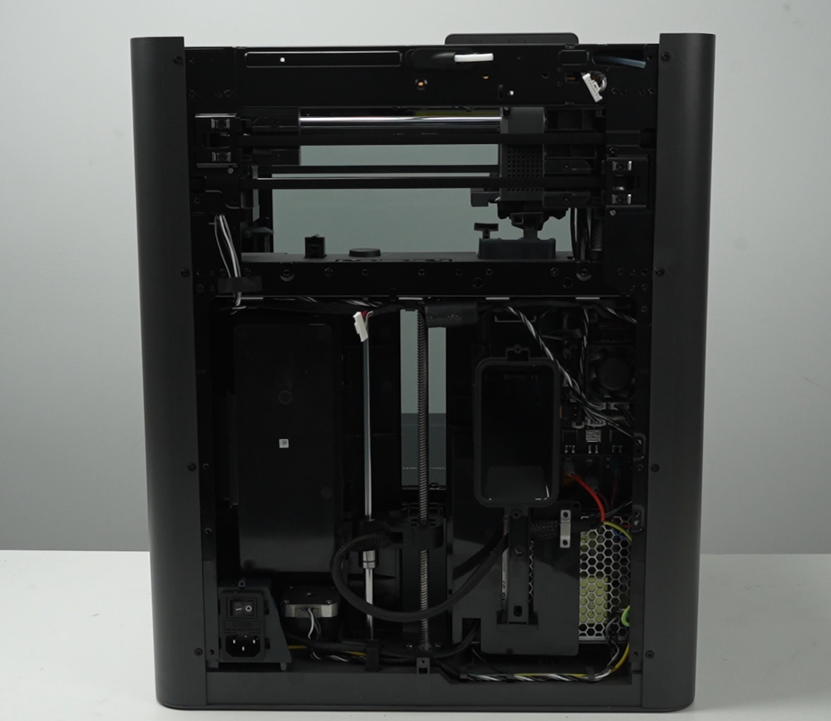
for Bambu MC Board - X2D
No se pudo cargar la disponibilidad para recoger
Utilice este texto para fomentar la comunicación o promover el intercambio en las redes sociales.
The MC board, or Main Control Board, is a printed circuit board with integrated microprocessors, various driver chips, connectors and circuits used to operate the various aspects of the X2D.
The full name of MC board is Main Control Board, usually called "main control board" in English. It is a printed circuit board integrated with a microprocessor, various driver chips, interfaces, and circuits.
In the Box
- MC Board *1
- BT2x5 Screw *3
Compatibility
X2D
MC Board and Cooling Fan Replacement Guide For the X2D
This article provides detailed steps for replacing the X2D MC Board and its cooling fan.
Applicable printer model
Bambu Lab X2D
When to Replace
1.Under normal power supply conditions, the main control board's indicator light does not flash;
2.Connector damage is obvious;
3.MC fan makes abnormal noise, does not work, or reports errors (replace the fan);
4.Bambu Lab service team confirmed through log files that there is an issue related to the main control board.
Safety Warning
⚠️ IMPORTANT!
It's crucial to power off the printer before conducting any maintenance work, including work on the printer's electronics and tool head wires. Performing tasks with the printer on can result in a short circuit, leading to electronic damage and safety hazards.
During maintenance or troubleshooting, you may need to disassemble parts, including the hotend. This exposes wires and electrical components that could short circuit if they contact each other, other metal, or electronic components while the printer is still on. This can result in damage to the printer's electronics and additional issues.
Therefore, it's crucial to turn off the printer and disconnect it from the power source before conducting any maintenance. This prevents short circuits or damage to the printer's electronics, ensuring safe and effective maintenance.
Remove the old MC board and MC Board Fan
Step 1. Remove the rear panel (including filament tube bracket & filament buffer)
Step 2. Remove the purge chute
Use an H1.5 allen key to remove the four fixing screws (BT2x5), then take off the purge chute.
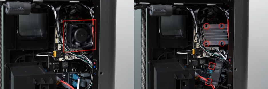
Step 3. Remove the MC Board Fan
Detach the rubber soft pins securing the MC Board Fan from the MC board's heat sink.
Gently pull the pins outwards.
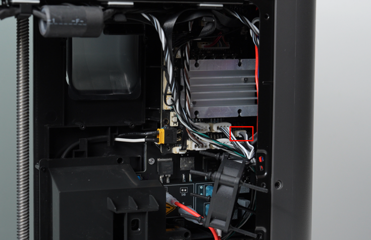
Step 3.1 Disconnect the Fan from the Board
Disconnect the MC Board Fan cable and remove the MC Board Fan.
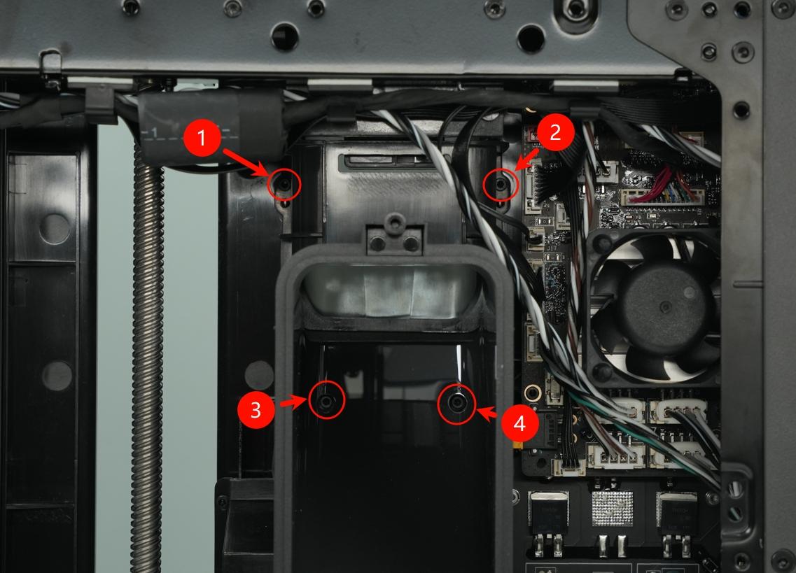
Step 4. Remove the MC board
Unplug all the connectors from the MC board, taking care not to damage any cables.
Disconnect all front-facing cables on the MC board.
ℹ️Note: Some plugs use locking tabs; you need to press the locking tab on top of the socket to unlock the plug before pulling it out.

Step 4.1 Remove the Stepper motor connectors
To prevent plugs from loosening during shipping, the three stepper motor plugs beneath the heat sink are reinforced with electronic silicone glue,
Use a sharp tool, such as tweezers, to remove the white glue before unplugging the cable connectors.

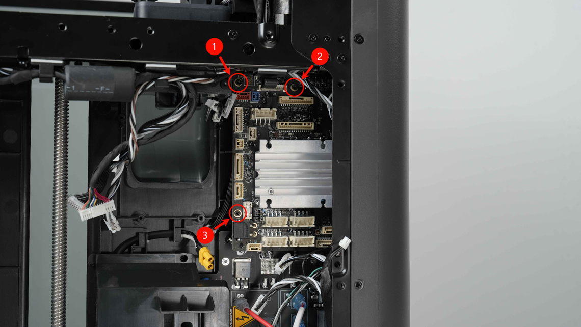
Step 4.2 Remove the MC Board
Remove the 3 screws on the MC board and take out the MC board.
Install the new MC board/ MC Board Fan
Step 1. Install the MC board
Carefully move the cables to the side, creating space to insert the MC board in the designated location, then tighten the 3 fixing screws.
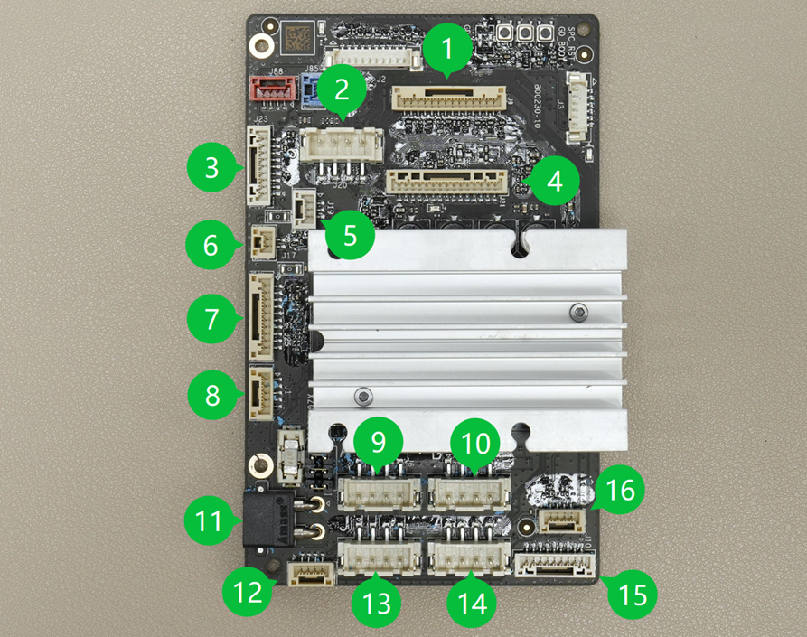
Step 2. Connect all the cables
Connect the cables. The MC board connector descriptions are as follows:

Step 3. Install the MC Board Fan
When installing the new fan, first install one end of the soft rubber pin onto the fan
Step 3.1 Connect the MC Board Fan
Connect the fan cable
Step 3.2 Install the MC Board Fan
Connect the soft rubber pins to the heat sink (sequence: upper right, lower right, lower left, upper left)

Step 4. Install the purge chute
Use an H1.5 allen key to install the four fixing screws (BT2x5) to secure the purge chute in place.
Step 5. Install the Rear Panel (including the filament tube bracket & filament buffer)
Verifying Success
✅ Connect power, turn on the printer, then perform device calibration; if calibration passes, the replacement is successful.