


for Bambu Lab Extruder Gear Assembly - H2S
No se pudo cargar la disponibilidad para recoger
Utilice este texto para fomentar la comunicación o promover el intercambio en las redes sociales.
The Extruder Gear Assembly precisely advances and controls filament movement, ensuring smooth printing and enabling filament changes when required.
Installation
Please learn about the installation on Bambu Lab Wiki.
In the Box
- Extruder Drive Gear*1
- Extruder Idler Gear*1
- Shim Washer*1
- Compression Washer*1
- Compression Spring*1
- M3-11 Screw*1
Compatibility
H2S and H2S Laser
Replace H2S Extruder Gear Assembly
Precautions:
Please be sure to follow the disassembly sequence outlined in this article strictly. Especially before removing the cover of the extruder, make sure to first remove the extruder filament sensor (handle with care to avoid pulling too hard), as failure to do so may result in the wiring of the sensor broken.

When to Use
Extruder gear failure.
Tools and Materials Needed
New extruder gear
Allen keys H2.0 and H1.5
Double-sided tape (recommended)
20 minutes
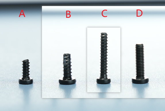
Screw List
Screw A: 2 screws for the filament sensor, BT2x6
Screw B: 4 screws for fixing the extruder unit front cover, BT3x8
Screw C: 1 screw for the cutter handle, BT2.6x14.5
Screw D: 1 side screw for the extruder, BT3x12
Safety Warning
IMPORTANT!
Before performing any maintenance on the printer or its electronic components (including toolhead cables), turn off the printer and disconnect the power supply to avoid short circuits, which may cause damage to electronic devices and safety hazards.
When maintaining or troubleshooting the printer, first check the temperature of the hotend and heatbed. Avoid operating at high temperatures. If high-temperature operation is necessary, wear heat-insulating gloves to ensure safe and effective maintenance.
If you have any questions about this guide, please click to submit a service ticket, and we will respond promptly to provide the help you need.
Disassembly Instructions
Step 1: Remove the Hotend
Refer to this tutorial to remove the hotend.
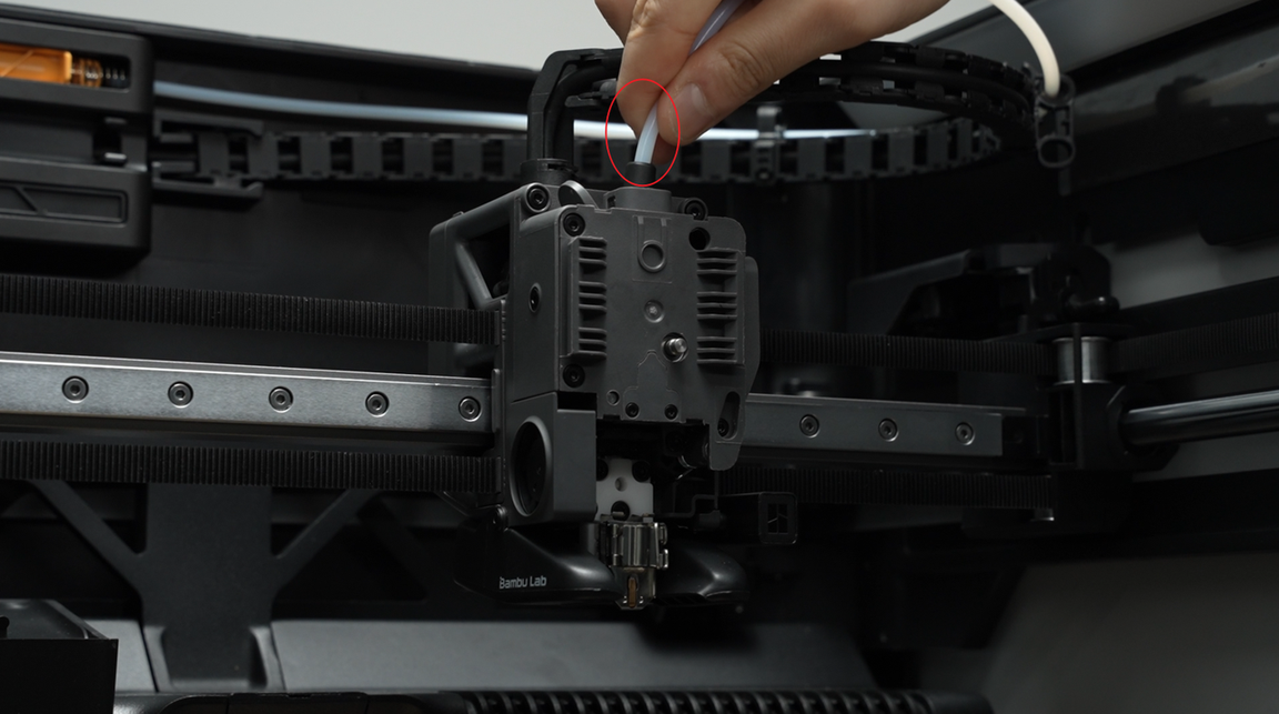
Step 2: Disconnect the PTFE Tube
Press the pneumatic connector to disconnect the PTFE tube;
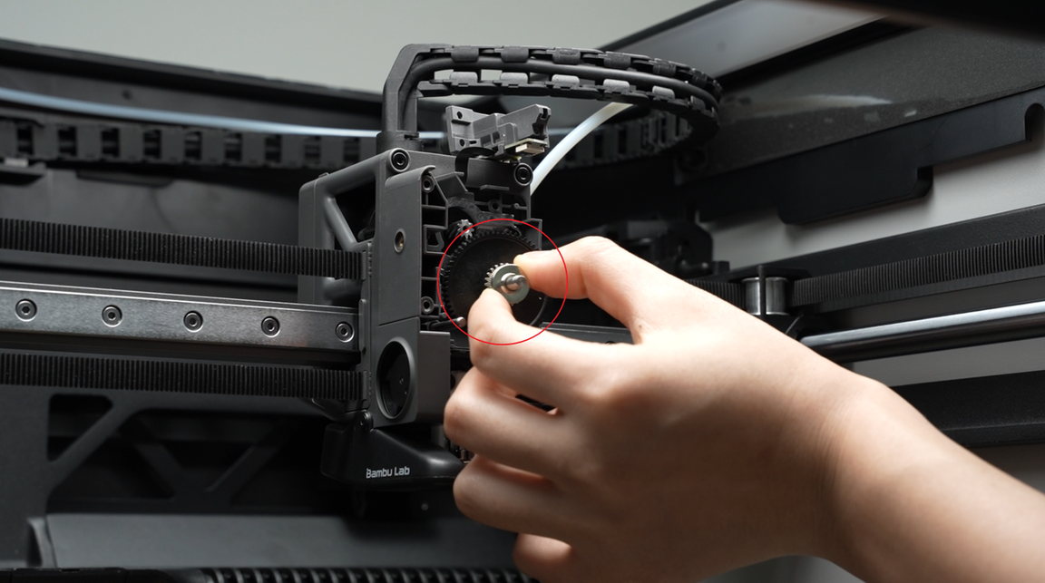
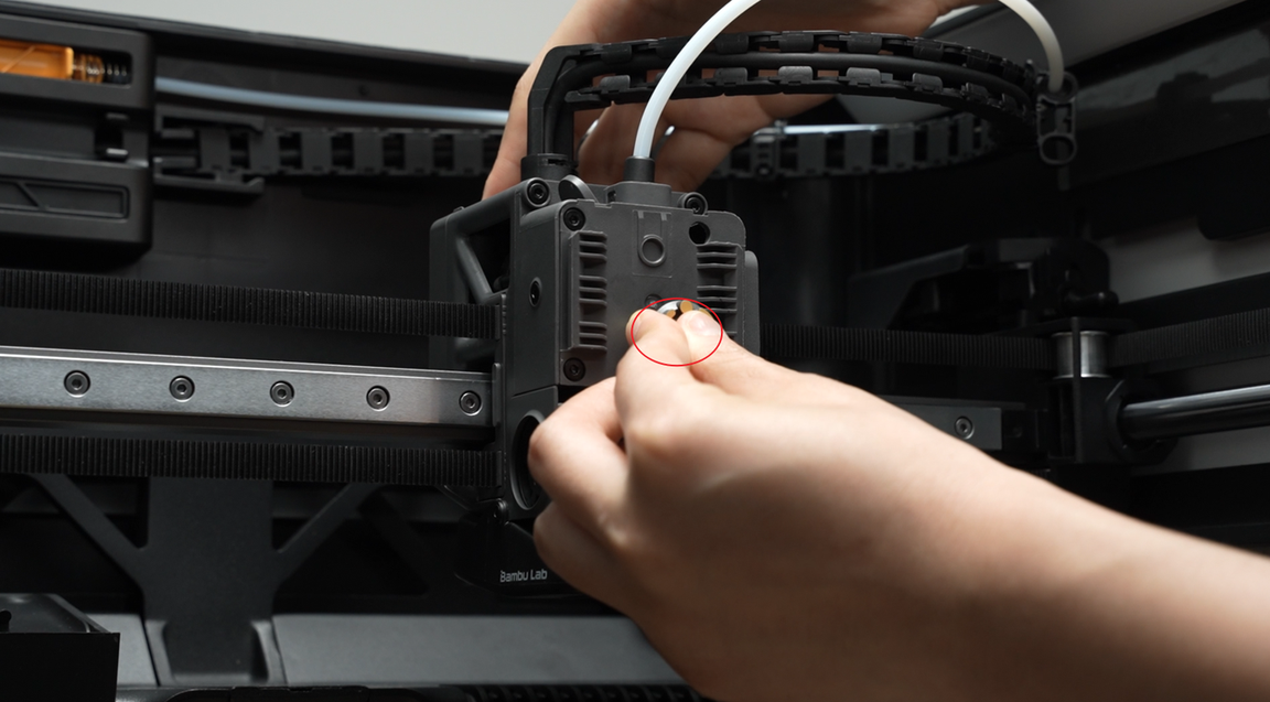
Step 3: Remove the Rotating Wheel
Rotate the rotating wheel and take it off.
Step 4: Loosen the Cutter Handle
Hold the cutter handle and use a screwdriver to remove 1 screw. After the screw is fully removed, gently release the cutter handle and let it hang naturally.

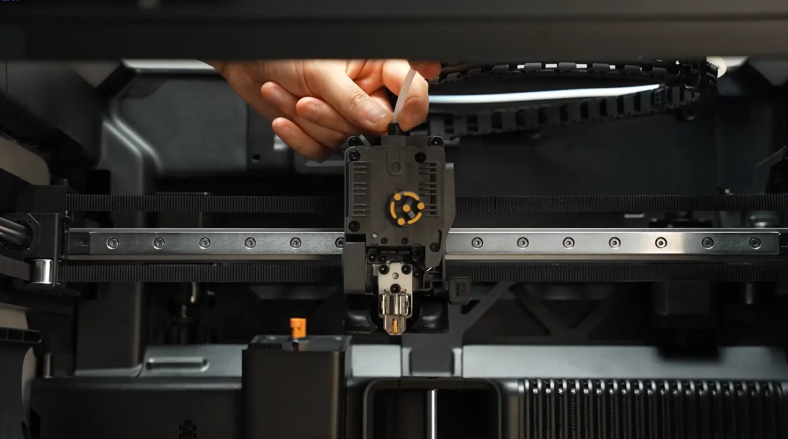
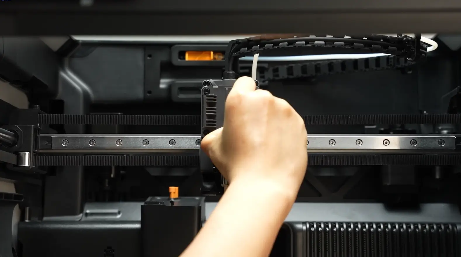
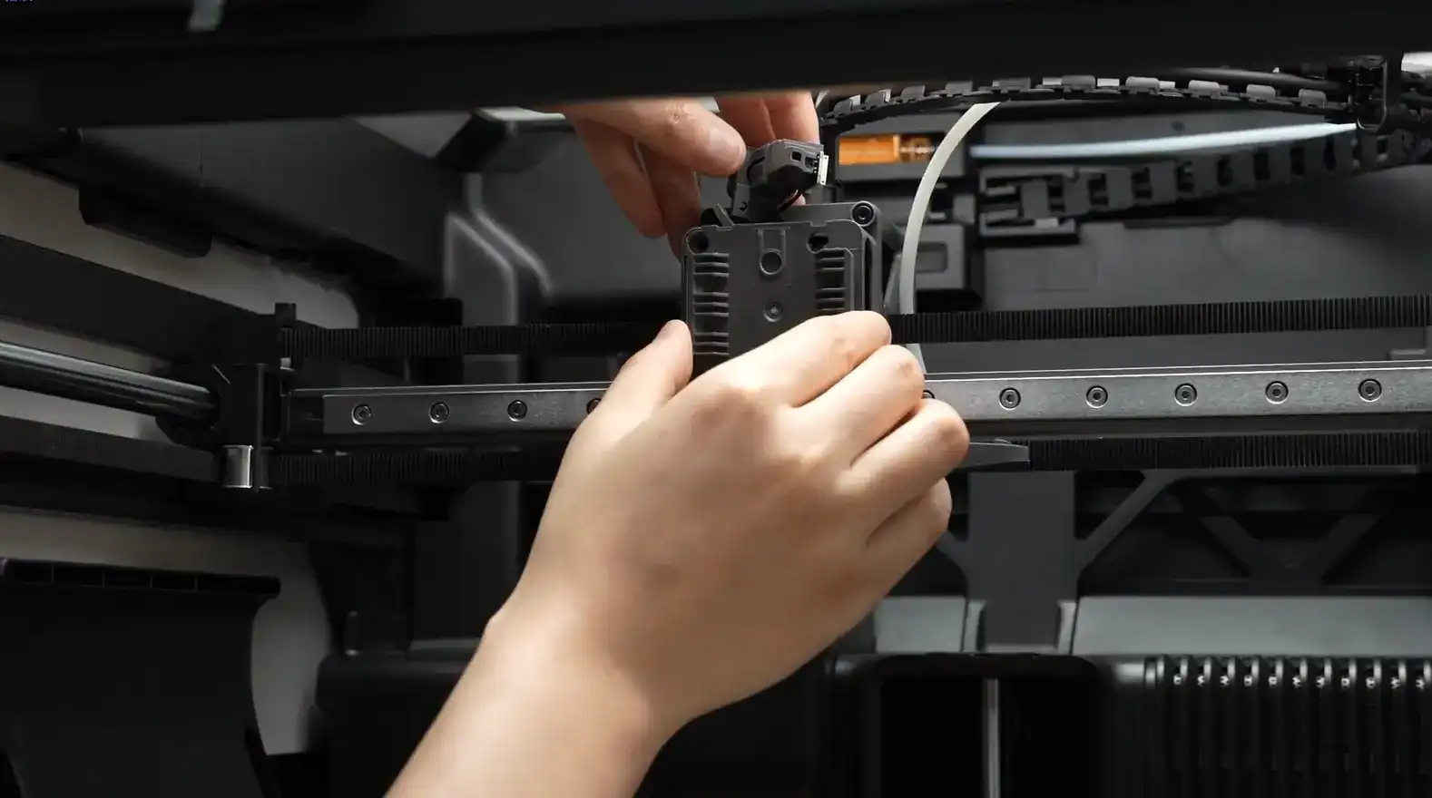
Step 5: Remove the Filament Sensor
Use an H2.0 Allen key to remove 2 screws. If possible, attach double-sided tape to the top of the toolhead to place the filament sensor, preventing it from falling during subsequent disassembly and assembly. Note: Do not pull hard when removing the filament sensor, and handle it carefully to avoid damaging the black FPC cable.

Step 6: Remove the Extruder Unit Front Cover
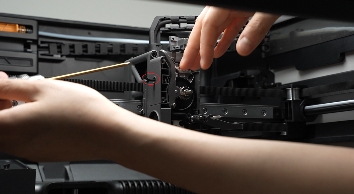
Use an H2.0 Allen key to loosen the tension driven lever locking screw on the side by one full turn;
Use an H2.0 Allen key to remove the 4 screws on the front cover.
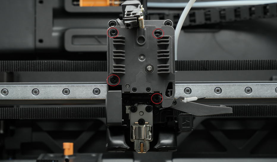
Remove the extruder unit front cover.
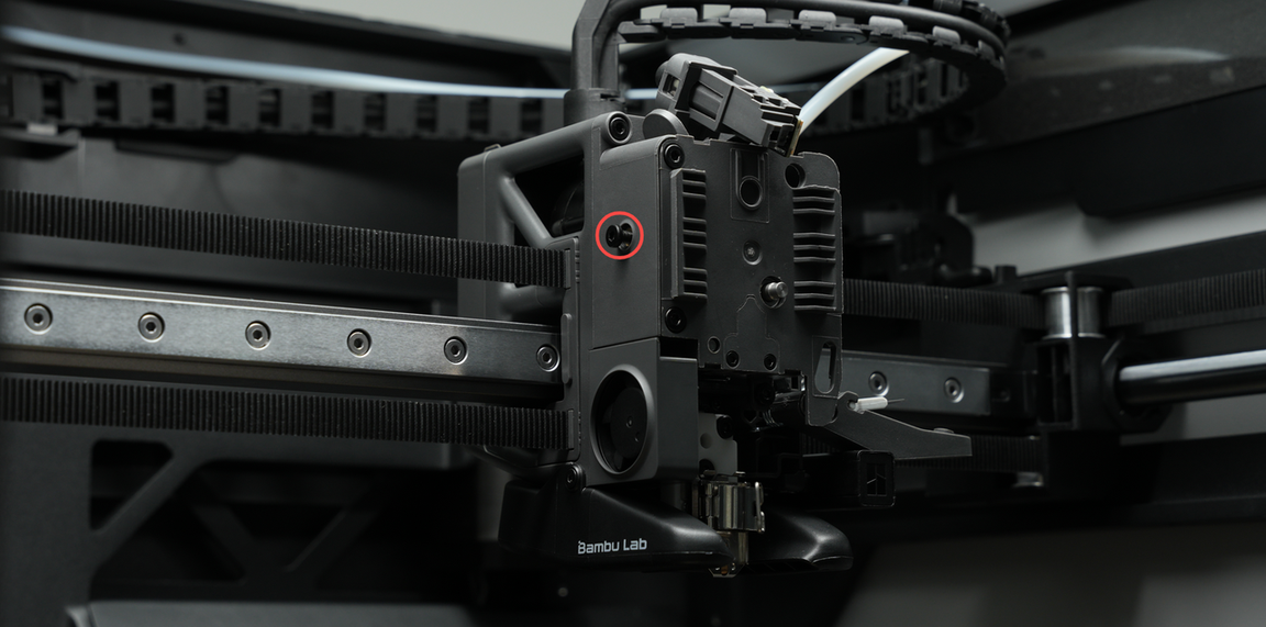
Step 7: Remove the Driven Wheel Bracket
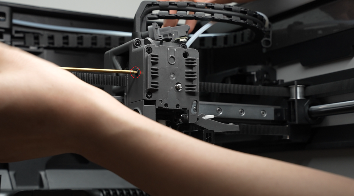
Use an H2.0 Allen key to remove the side screw. The internal spring and end cap may easily fall off when removing the bracket, so handle it carefully to prevent loss.

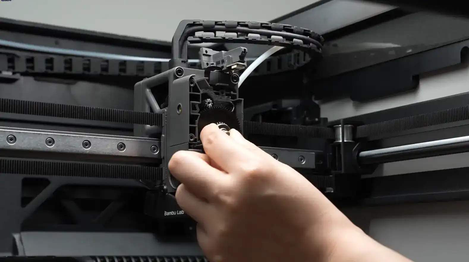
Step 8: Remove the Extruder Gear
Gently shake the large extruder gear and pull it out directly.
Assembly Instructions
Step 1: Install the Extruder Gear
Install the extruder gear.
Step 2: Install the Driven Wheel Bracket
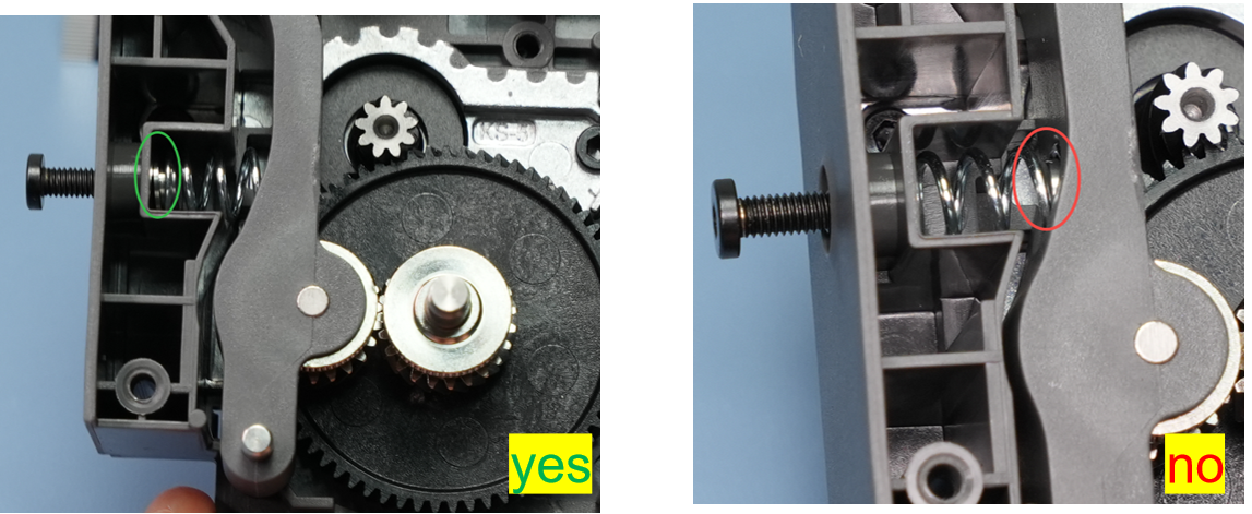
Mount the driven wheel bracket onto the corresponding rotating shaft. Assemble the spring and end cap in the correct orientation and position (refer to the correct and incorrect examples below), place them in the corresponding position on the driven wheel bracket, and screw in the side screw to hold them in place—do not fully tighten yet.
IMPORTANT!
Ensure the spring and end cap are installed correctly; otherwise, the extruder may fail to grip the filament, leading to printing errors.

Left: Correct demonstration, with the screw pressing against the concave surface of the end cap;
Right: Incorrect demonstration, with the end cap in the wrong position, preventing the spring from being compressed.
Pre-lock the side screw by 2-3 turns—do not fully tighten, as this may hinder front cover installation.
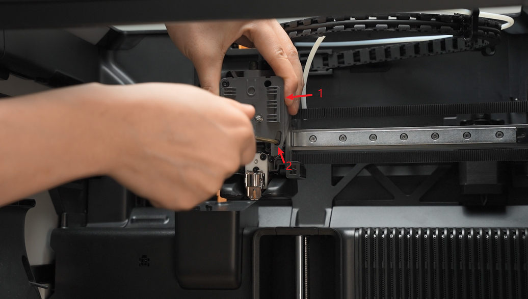
Step 3: Install the extruder unit front cover
Reattach the extruder unit front cover and screw in the 4 front cover screws.

Tighten the extruder side screw;
Step 4: Install the filament sensor
When installing the extruder filament sensor, make sure the black FPC cable is not bent and is placed smoothly into the gap. Then fasten the extruder filament sensor with 2 screws.

When assembling, be careful not to pinch the sensor cable. Use your finger or a plastic tool to move the cable away from the screw holes. Before tightening the screws, check the holes from the top to ensure the cable is not blocking them.

Step 5: Reattach the Cutter Handle
Before re-tightening the screw, hold the cutter handle firmly in position. When tightening the screw, avoid excessive force to prevent thread stripping.
Step 6: Connect the PTFE Tube
Insert the PTFE tube.
Step 7: Reinstall the Rotating Wheel
Reattach the rotating wheel.
Step 8: Install the Hotend
Refer to this tutorial to install the hotend.
How to Verify Completion/Success
Turn the printer back on and control filament filamenting and retraction via the screen to confirm proper operation.