


for Bambu Auxiliary Extruder Upper Cover Assembly /Extruder Gear Assembly - X2D
No se pudo cargar la disponibilidad para recoger
Utilice este texto para fomentar la comunicación o promover el intercambio en las redes sociales.
Auxiliary Extruder Gear Assembly
Installed inside the auxiliary extruder, driven by the extruder motor, this gear assembly feeds the filament to the hotend or retracts it from the auxiliary extruder.
In the Box
- Active Gear *1
- Passive Gear *1
- Spring *1
- Spring Plate *1
- 693ZZ Bearing *1
- M3x8 Screw *1;
Compatibility
X2D

Auxiliary Extruder Upper Cover Assembly
Installed at the top of the auxiliary extruder and used to secure the auxiliary extruder gear assembly. It includes the auxiliary extruder filament inlet.
In the Box
- Auxiliary Extruder Top Cover *1
- MR104ZZ Bearing *1
- BT2x5 Screw *9
Compatibility
X2D
Auxiliary Extruder Gear Assembly

Auxiliary Extruder Replacement Guide for the X2D
This page introduces how to replace the X2D Auxiliary Extruder
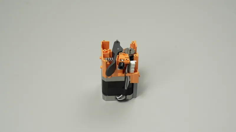
Auxiliary Extruder
🔎 Find the X2D Auxiliary Extruder in the Bambu Lab store.
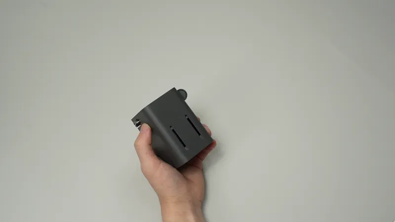
The auxiliary extruder is installed at the back of the printer and is used to control the feeding, stopping, and retraction of support filament.
Auxiliary Extruder Upper Cover Package
Auxiliary Extruder Upper Cover
Fixing Screws (×5)
Installed at the top of the auxiliary extruder, used to secure the auxiliary extruder gear assembly and includes the auxiliary extruder filament inlet.
## Applicable printer model
Bambu Lab X2D
When to Replace
Common situations requiring auxiliary extruder replacement:
Extruder motor malfunction, unable to operate
Damaged auxiliary extruder cables or connectors
Common situations requiring replacement of the auxiliary extruder upper cover:
Physical damage affecting product use
Common situations requiring replacement of the auxiliary extruder gear assembly:
Gear wear or bearing wear causing printing anomalies
Common situations requiring replacement of the auxiliary extruder housing:
Physical damage affecting product use
Required Tools and Materials
1.New auxiliary extruder upper cover, auxiliary extruder gear assembly, or auxiliary
extruder housing
2.H 1.5 allen key
3.H 2.0 allen key
4.Wrench
5.Tweezers
Safety Warning
⚠️ IMPORTANT!
It's crucial to power off the printer before conducting any maintenance work, including work on the printer's electronics and tool head wires. Performing tasks with the printer on can result in a short circuit, leading to electronic damage and safety hazards.
During maintenance or troubleshooting, you may need to disassemble parts, including the hotend. This exposes wires and electrical components that could short circuit if they contact each other, other metal, or electronic components while the printer is still on. This can result in damage to the printer's electronics and additional issues.
Therefore, it's crucial to turn off the printer and disconnect it from the power source before conducting any maintenance. This prevents short circuits or damage to the printer's electronics, ensuring safe and effective maintenance.
Remove the Auxiliary Extruder
Step 1. Remove the auxiliary extruder
Press the filament inlet pneumatic connector and pull out the filament PTFE tube.
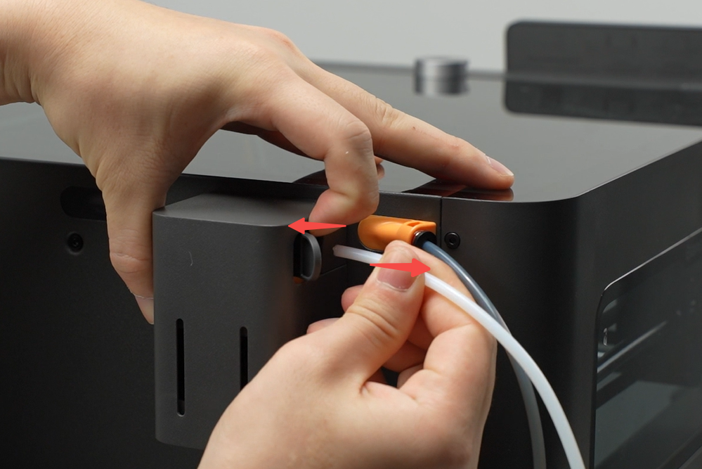
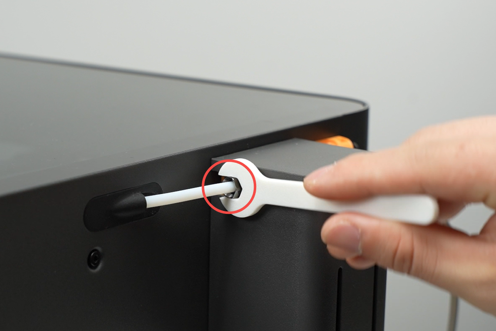
Use an 8mm open-end wrench to loosen the locking nut at the auxiliary extruder filament outlet and remove the tube.
ℹ️ Note: If resistance is too high when removing the tube, pull the tube from inside the printer.
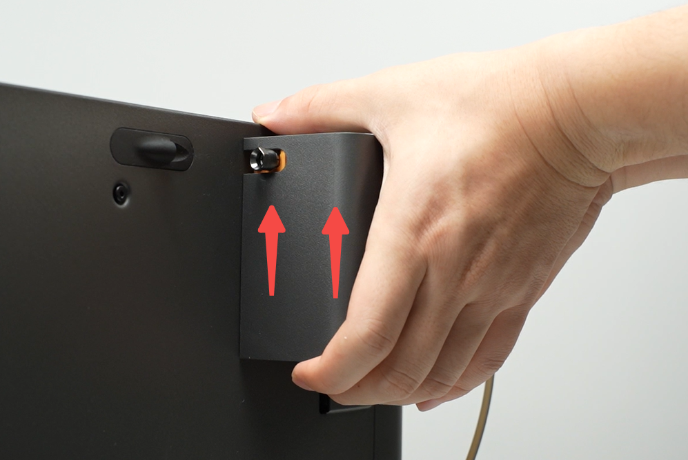
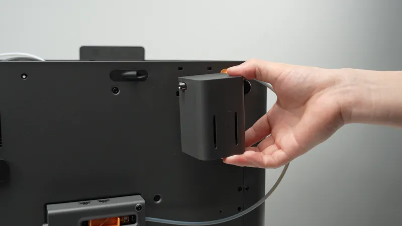
Support the auxiliary extruder with your hand and gently push upwards to unlock it from the printer.
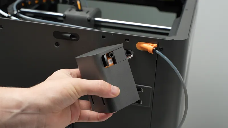
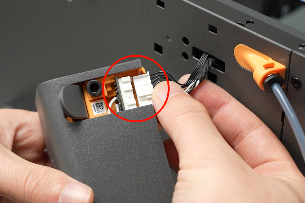
Remove the connector cover on the auxiliary extruder, press the connector plug locking tab to disconnect the cable, then remove the auxiliary extruder unit.
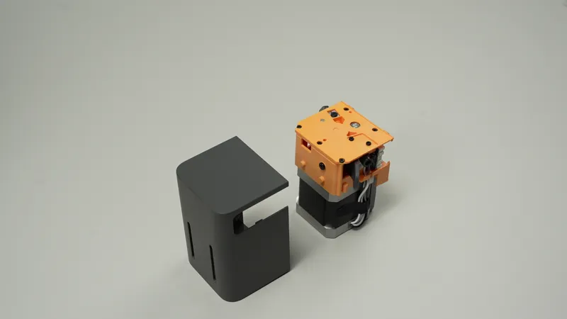
Step 2. Remove the auxiliary extruder housing
Align the allen key to the slot at the back of the auxiliary extruder, push the extruder motor forward to unlock and push out internal components, then remove the housing.
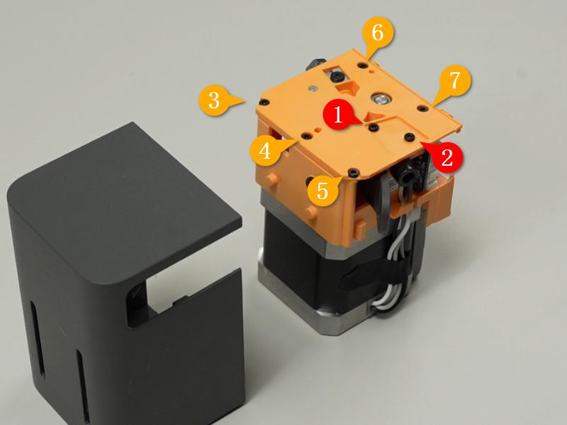
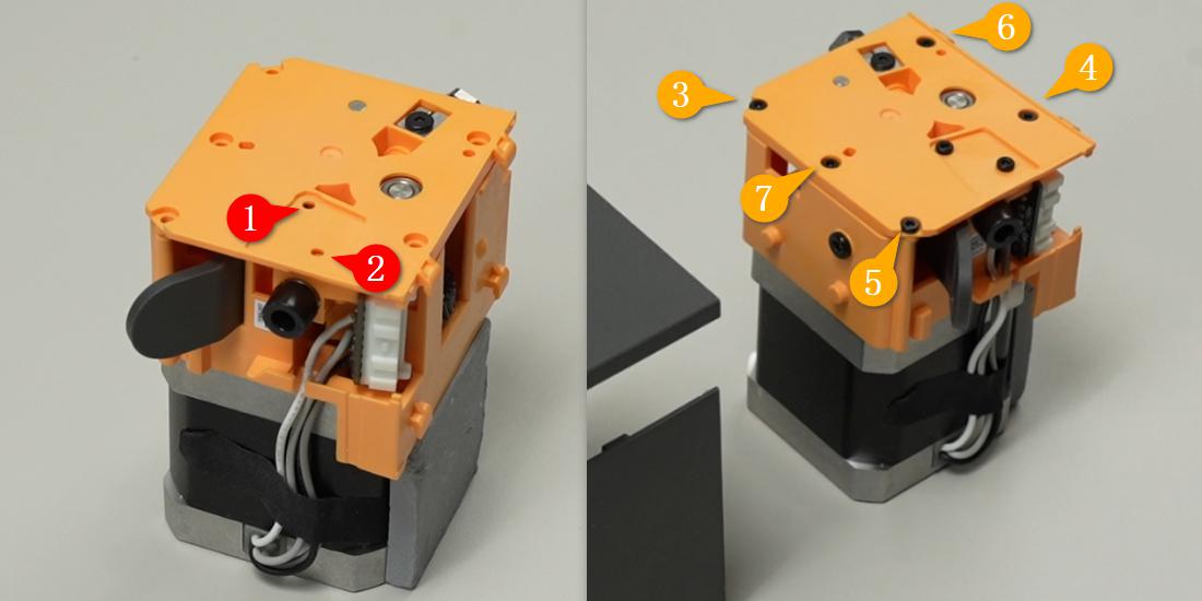
Step 3. Remove the auxiliary extruder upper cover
Use an H1.5 allen key to remove seven fixing screws and take off the auxiliary extruder upper cover.
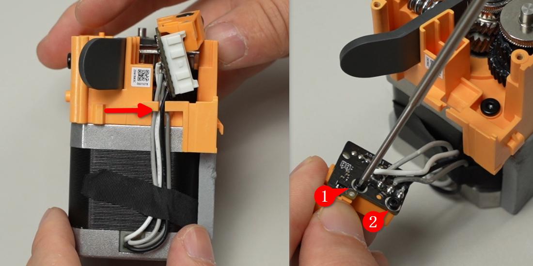
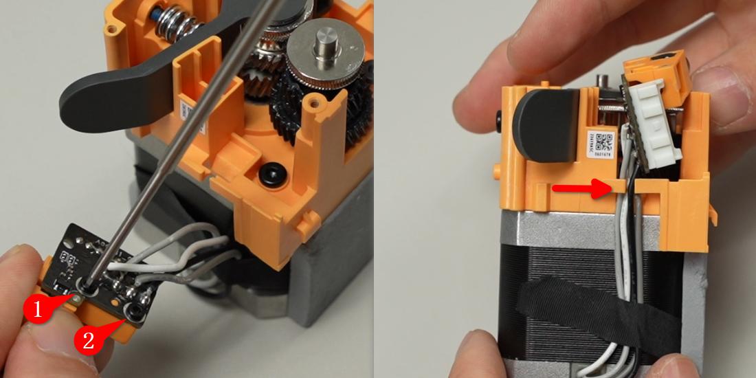
Loosen the motor connector cable from the locking tab, use an H1.5 allen key to remove two fixing screws, and remove the tube connector accessory.
This operation is only required when the pneumatic connector or its structural parts suffer physical damage.
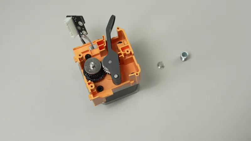
Step 4. Remove the auxiliary extruder gear assembly
Use an H2.0 allen key to remove one fixing screw.
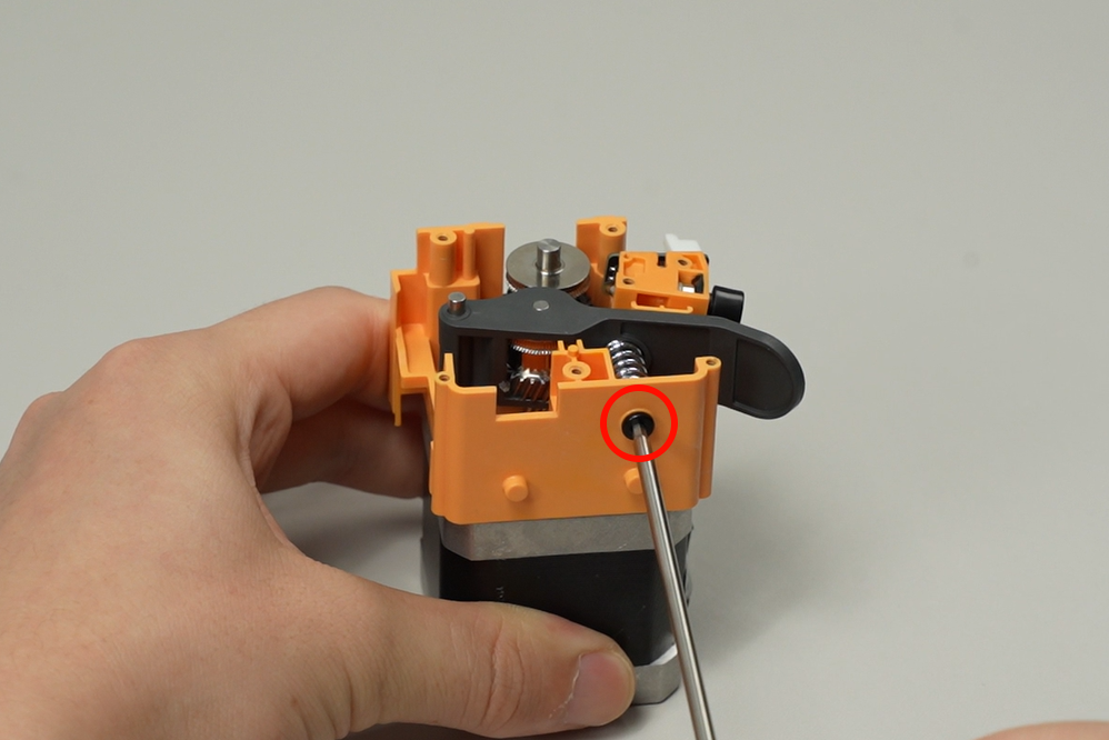
Remove the auxiliary extruder driven gear, drive gear, spring, and pressure plate.
Auxiliary Extruder:
Step 1. Install the auxiliary extruder gear assembly
Install the auxiliary extruder drive gear and driven gear respectively, then use your hands or tweezers to install the pressure plate and spring together (the raised side of the pressure plate should face the spring, and the grooved side should face the threaded hole), then tighten one fixing screw with an H2.0 allen key.
Step 2. Install the auxiliary extruder upper cover
Install the pneumatic connector onto the motor connector and organize the cables.
Install the auxiliary extruder upper cover onto the auxiliary extruder, and tighten the seven screws in the sequence shown using an H1.5 allen key.
Step 3. Install the auxiliary extruder housing
Slide the assembly into the housing by aligning the auxiliary extruder driven gear handle direction along the auxiliary extruder housing installation slot.
Connect the cable to the auxiliary extruder connector, ensuring the locking tab direction is correct.
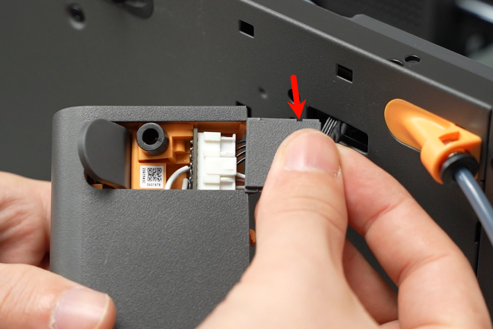
Insert the connector cover into the auxiliary extruder, making sure the cover’s notch faces outwards from the auxiliary extruder during insertion.
First retract the cable into the slot, then insert the auxiliary extruder into the hole at the back of the printer and press down to lock it in place.
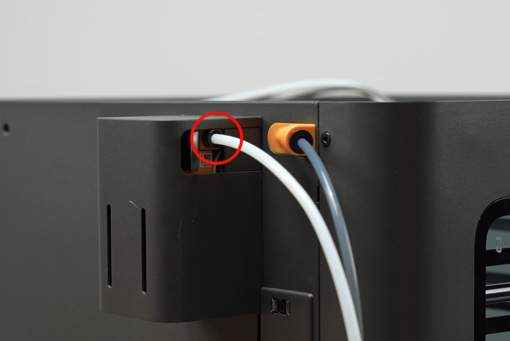
Loosen the locking nut on the left filament outlet of the auxiliary extruder, insert the PTFE tube from the top center of the printer's rear panel into the filament outlet about 22mm, then use an 8mm open-end wrench to tighten the auxiliary extruder filament outlet locking nut.
(Please ensure the PTFE tube is fully inserted, otherwise filament may buckle inside the extruder.)
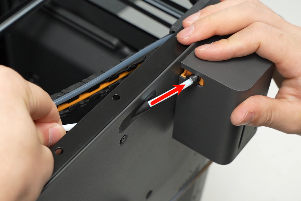
Insert the white PTFE tube into the auxiliary extruder filament inlet.
Verifying Success
✅ Connect the power, turn on the printer, and check if the auxiliary extruder can load and unload filament properly.
If you encounter any issues, please retrace your steps and check all connections before trying again. If the problems persist, please contact the Bambu Lab service team for further assistance.