


Extruder Filament Sensor/ Extruder Unit Front Cover Assembly for Bambu X2D
No se pudo cargar la disponibilidad para recoger
Utilice este texto para fomentar la comunicación o promover el intercambio en las redes sociales.
Extruder Filament Sensor Left
The extruder filament sensor - left is installed on the upper left part of the extruder and is responsible for detecting the filament presence.
In the Box
- Left Hall Detection Board *1;
- BT2x5 Screw *2
Compatibility
X2D

Extruder Filament Sensor Right
The extruder filament sensor - right is installed on the upper right part of the extruder and is responsible for detecting the filament presence.
In the Box
- Right Hall Detection Board *1;
- BT2x5 Screw *1
Compatibility
X2D

Extruder Unit Front Cover Assembly
The outer plastic shell of the extruder.
In the Box
- Extruder Front Cover *1;
- Filament Press Block *1
- 693ZZ Bearing *1
- BT3x7 Screw *3
- BT2x8 Screw *1
Compatibility
X2D

Extruder components Replacement guide for the X2D
This article provides detailed steps for replacing the X2D extruder components.
The X2D extruder is equipped with four independent accessories, namely:
Left filament sensor board: Installed on the upper part of the left extruder, this accessory detects filament status.
Right filament sensor board: Installed on the upper part of the right extruder, this accessory detects filament status.
Extruder gear ( P2S): Installed inside the extruder and driven by the extruder motor, this gear assembly feeds filament to the hotend or retracts it from the extruder.
Extruder unit front cover: The outer shell of the extruder.
Applicable printer model
Bambu Lab X2D
When to Replace
Common situations requiring replacement of the extruder gear assembly:
Gear wear or bearing wear causing
printing anomalies
Replacement of the gear assembly is determined necessary by Bambu Lab technical support.
Common situations requiring replacement of the filament sensor switch assembly:
Failure of filament detection functionality
Ribbon cable broken or damaged
Common situations requiring replacement of the extruder unit front cover assembly:
Physical damage affecting product use
Required tools and materials
Wrench
H1.5 allen key
H2.0 allen key
Needle nose pliers
Safety Warning
⚠️ IMPORTANT!
It's crucial to power off the printer before conducting any maintenance work, including work on the printer's electronics and tool head wires. Performing tasks with the printer on can result in a short circuit, leading to electronic damage and safety hazards.
During maintenance or troubleshooting, you may need to disassemble parts, including the hotend. This exposes wires and electrical components that could short circuit if they contact each other, other metal, or electronic components while the printer is still on. This can result in damage to the printer's electronics and additional issues.
Therefore, it's crucial to turn off the printer and disconnect it from the power source before conducting any maintenance. This prevents short circuits or damage to the printer's electronics, ensuring safe and effective maintenance.
Remove the Old Extruder Components
Step 1. Remove the toolhead housing
Step 2. Remove the hotend
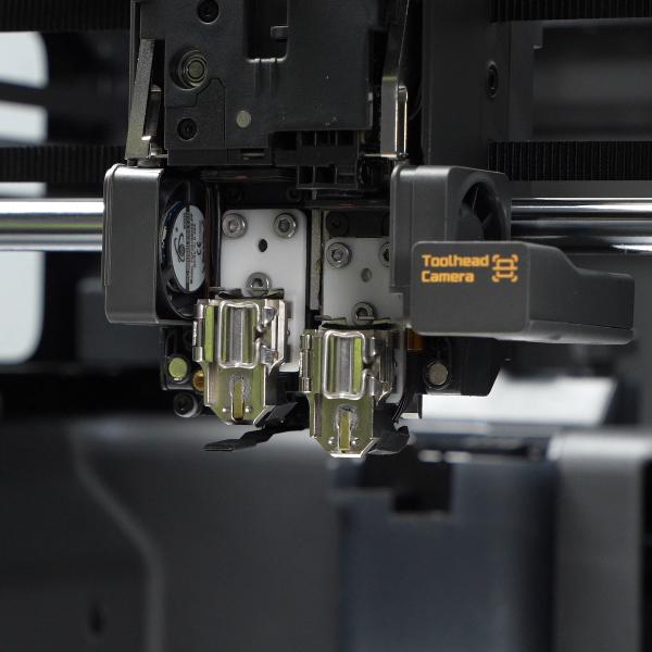
Step 3. Remove the left and right filament cutter lever assemblies
Remove the screws of the left filament cutter lever assembly, spread the lever outward, and nest it in a position that does not interfere with subsequent operations.
 Remove the screws of the right filament cutter lever assembly, spread the lever outward, and nest it in a position that does not interfere with subsequent operations.
Step 4. Remove the PTFE tubes
Press the pneumatic connector on the left filament sensor board and pull out the PTFE tube.
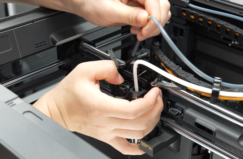
Push the lever of the flow blocker assembly to the right to expose the pneumatic connector on the right filament sensor board, loosen the connector counterclockwise with a wrench, and pull out the PTFE tube.

Step 5. Remove the hotend heating assembly and other cables
Remove the screws mounting the hotend heating assembly interface board bracket, remove the bracket, then disconnect the hotend heating assembly connector.
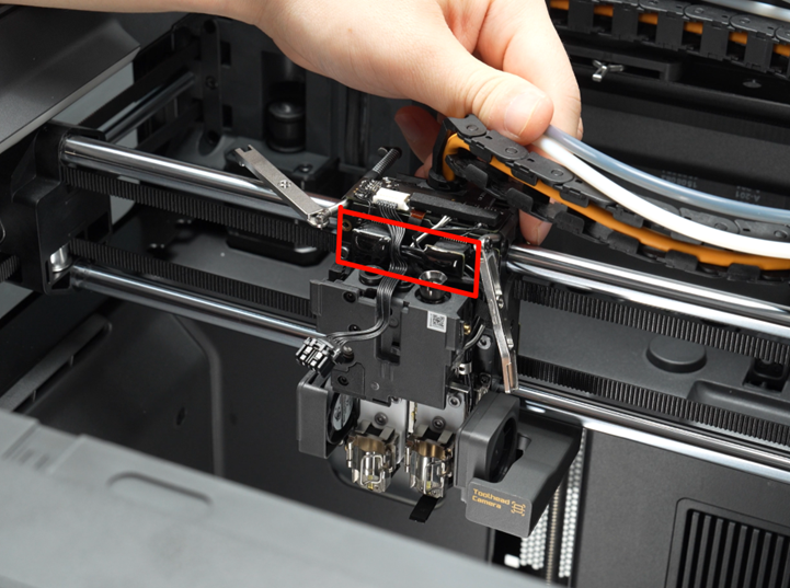
Remove the wiring foam and disconnect the connectors on the toolhead interface board (except for the logo LED cable).

Remove all cables from the cable ducts and nest them in positions that do not interfere with subsequent operations.
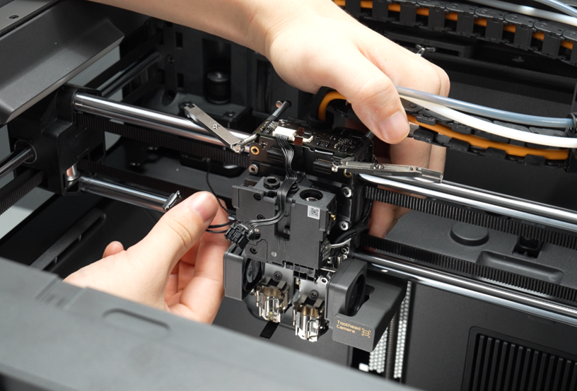
Step 6. Remove the left hotend cooling fan
Remove the two screws securing the left hotend cooling fan and take off the fan.

Step 7. Remove the extruder unit front cover
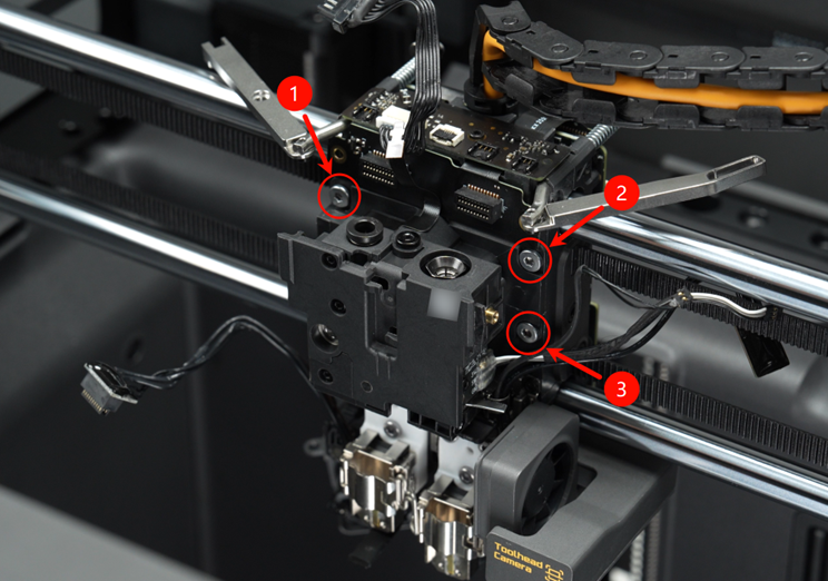
Remove the 3 screws of the extruder unit front cover,
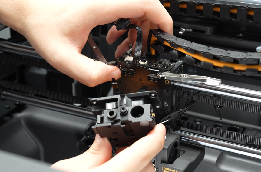
Gently separate the extruder unit front cover assembly from the toolhead, while lightly pressing the hotend heating assembly interface board to prevent excessive cable pulling that may cause damage.
Lift up to release the extruder unit front cover assembly, leaving the right filament sensor board on the toolhead.
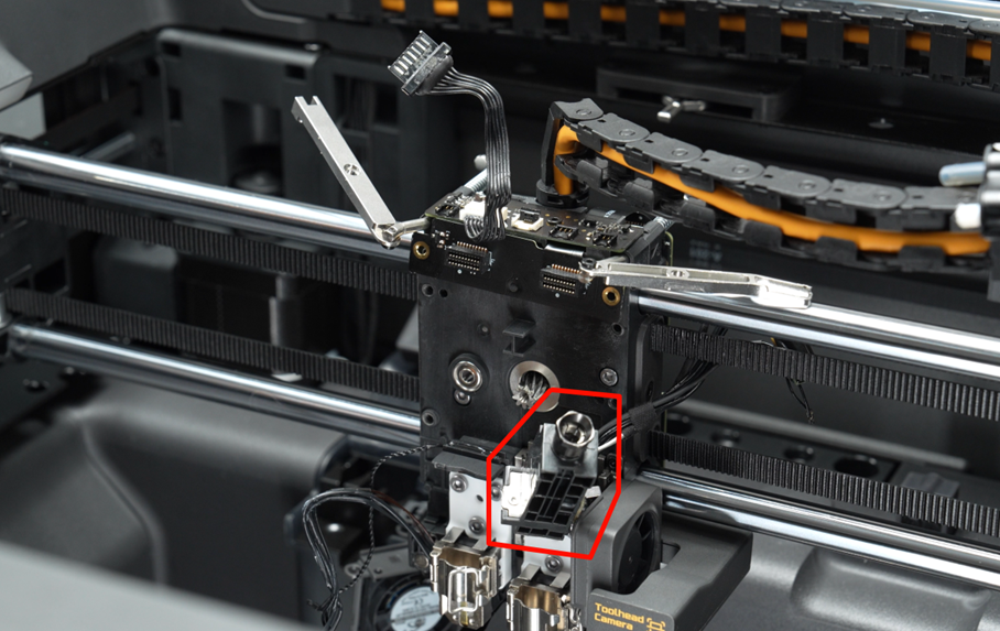
Step 8. Remove the right filament sensor board
Tear off the acetic acid tape from the wiring and remove the right filament sensor board.

Step 9. Detach the extruder gear assembly
Hold the large drive gear on the extruder by hand and remove the extruder gear.

Remove the screw of the driven gear pressure block located above the extruder unit.
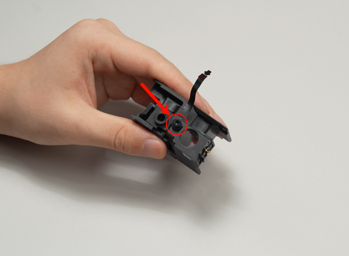
Remove the driven gear pressure block, then remove the driven gear assembly using pliers or tweezers.
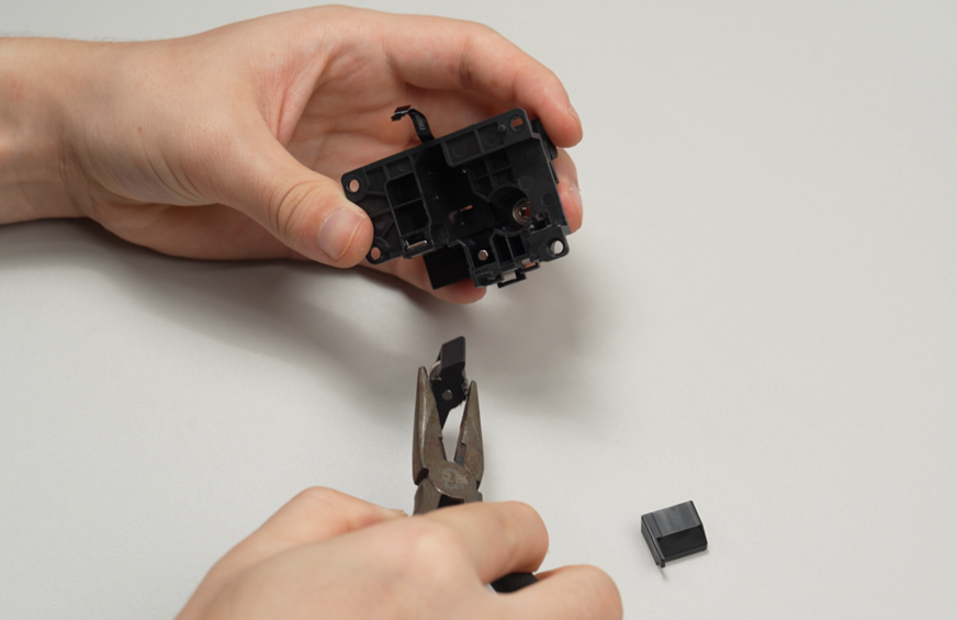
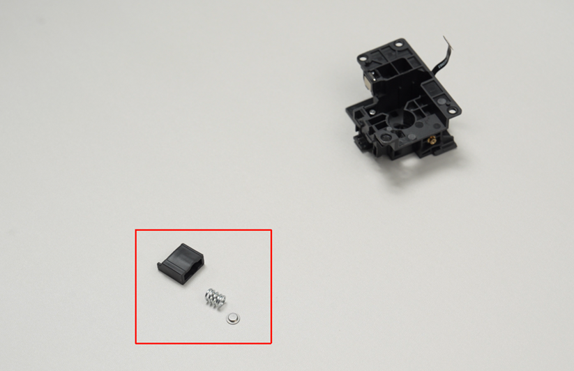
Take out the spring and pressure plate from the driven gear pressure block.
 Step 10. Remove the left cutter assembly
Remove the cutter plate screw with a screwdriver and take off the cutter plate.
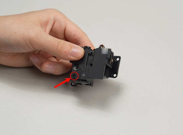 Remove the left cutter assembly.

Step 11. Remove the left filament sensor board
Remove the two screws of the left filament sensor board on the extruder unit,
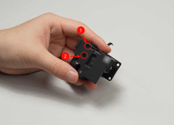 hold the pneumatic connector on the left filament switch board, lift up and remove the left filament sensor board,
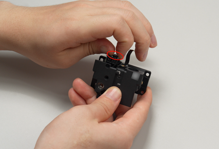 detach the cable and the extruder unit front cover (the cable has adhesive backing; peel it off gently), detaching the left filament sensor board from the extruder unit front cover.

Install the New Extruder Components
Step 1. Install the extruder gear assembly
Install the extruder driven gear assembly through the shaft in the direction shown into the extruder unit front cover,
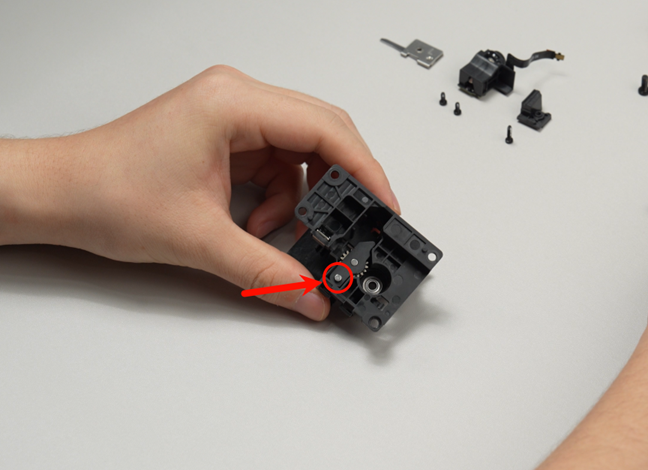
pick up the driven gear pressure block, place the spring inside,

position the pressure plate with the raised side facing the spring, and place the entire driven gear pressure block as shown, into the extruder unit front cover,
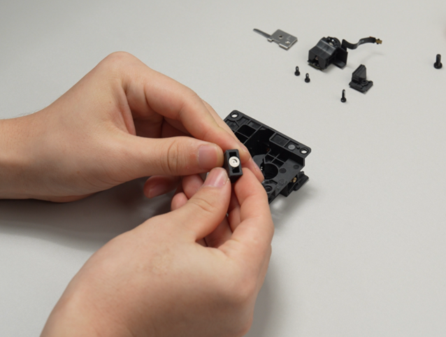
install the main extruder gear into the extruder unit front cover,
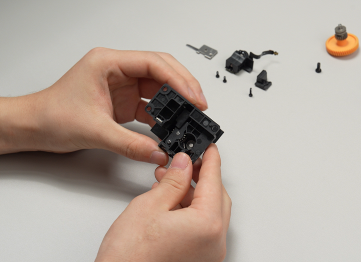
secure the screw fixing the pressure block.
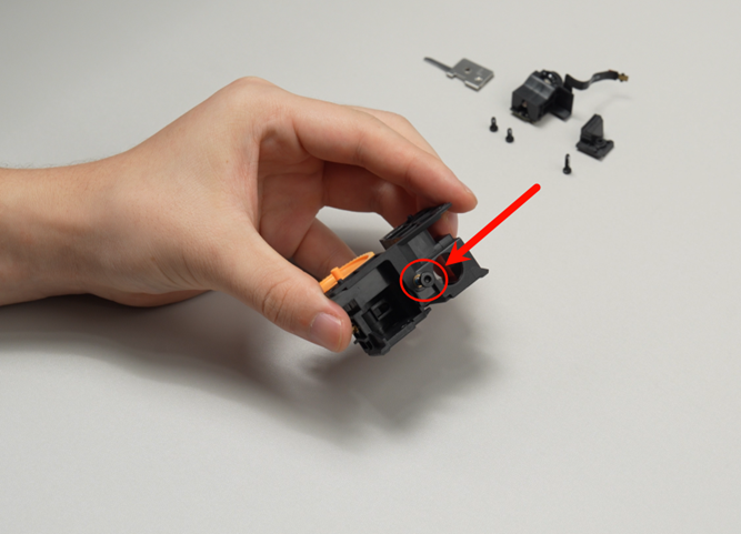
Step 2. Install the left cutter assembly
Nest the left cutter assembly into the groove below the extruder unit front cover as shown,
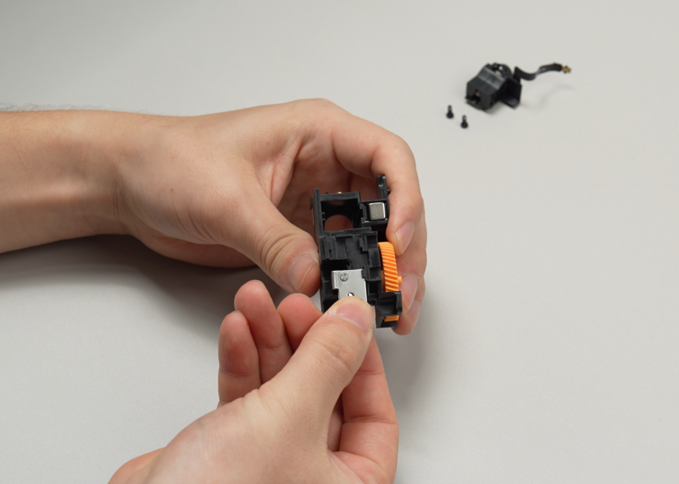
install the cable pressure block onto the extruder unit front cover and tighten one screw.

Step 3. Install the left filament sensor board
Nest the left filament sensor board in the left slot of the extruder unit front cover and press it into place.
Note: The filament sensor board (green PCB) should face left, with the cable facing rearward to avoid incorrect installation direction.
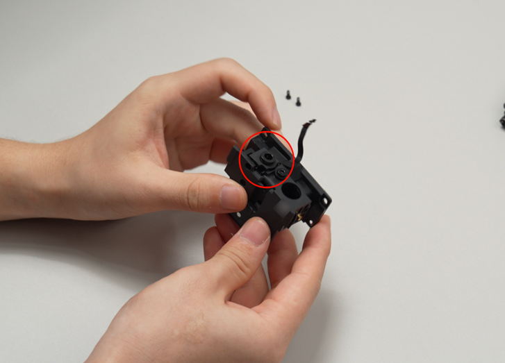
Install the two screws of the left filament sensor board.
Step 4. Install the right filament sensor board
Push the right filament sensor board upwards into the extruder unit front cover from the bottom as shown, pushing it fully in.
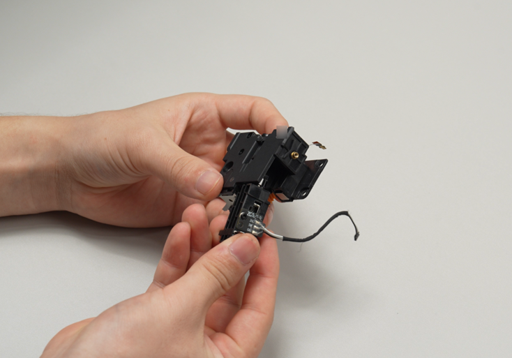
Push the lever of the flow blocker assembly below the toolhead to the left to lower the right filament sensor board.
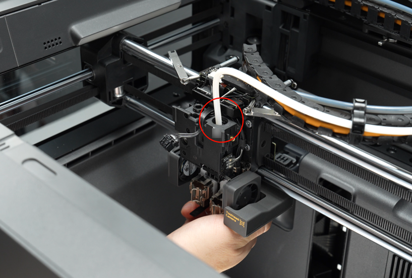
Step 5. Install the extruder unit front cover
Nest the extruder unit front cover onto the toolhead front carriage; please hold the right filament sensor board by hand to prevent it from falling out.
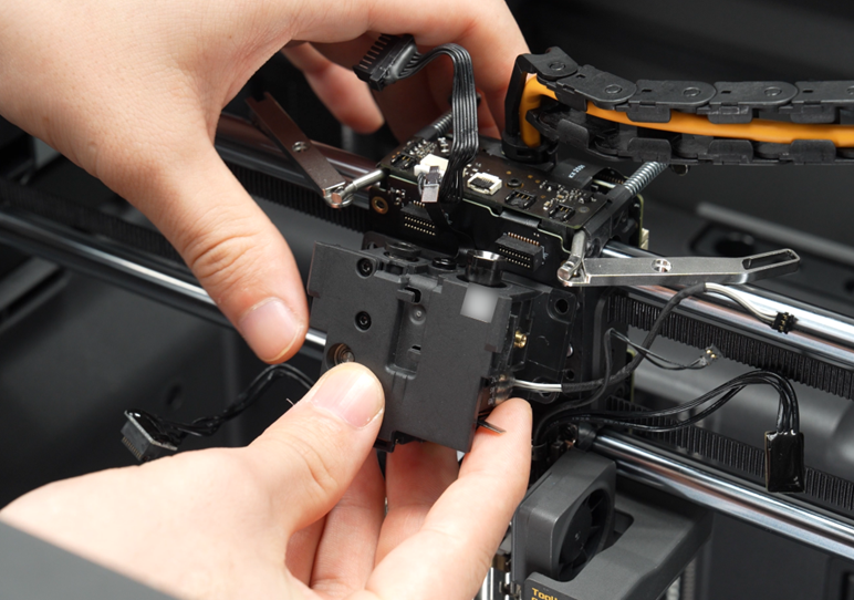
Tighten the 3 screws of the extruder unit front cover.
Bundle the right filament sensor board cable together with other cables using acetic acid tape, nest them in the right cable duct.
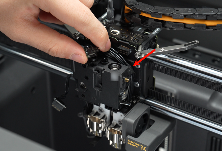
Nest the cables on the left side in the left cable duct, paying attention to insert the thinner Eddy Current Coil cables first.

Step 6. Install the left hotend cooling fan
Nest the left hotend cooling fan into place and tighten the 2 fixing screws.
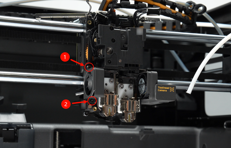
Step 7. Connect the cables
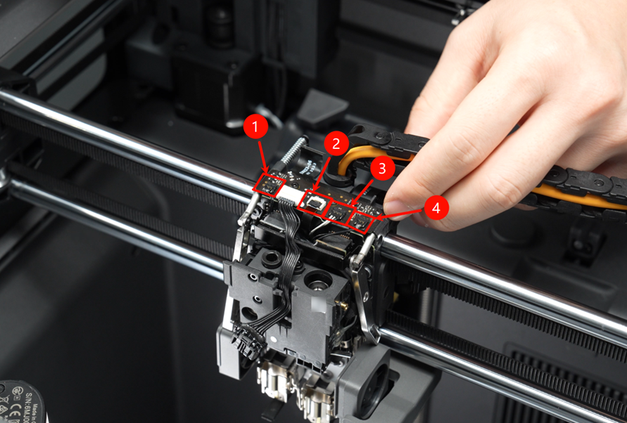
Connect the cables of the toolhead interface board and the hotend heating assembly interface board, then reattach the foam padding.
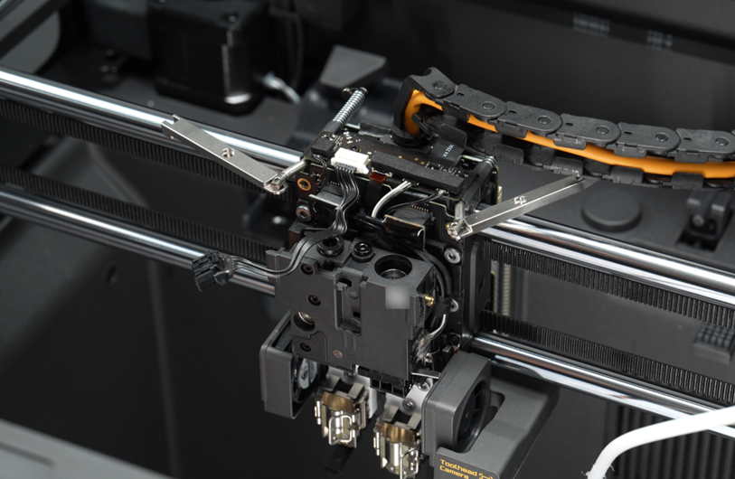
Cable interfaces of the toolhead interface board are as follows:

Install and secure the bracket of the hotend heating assembly interface board with 2 screws.
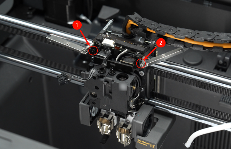
Note: Cables of the left Eddy Current Coil, left filament sensor board, right filament sensor board, and right Eddy Current Coil should all run under the bracket.
Step 8. Install the PTFE tubes
Push the flow blocker assembly to the right to expose the pneumatic connector on the right filament sensor board, nest the PTFE tube into place, then use the printed wrench to tighten the pneumatic connector clockwise to secure the PTFE tube, finally push the flow blocker assembly to the left to lower the right filament sensor board.
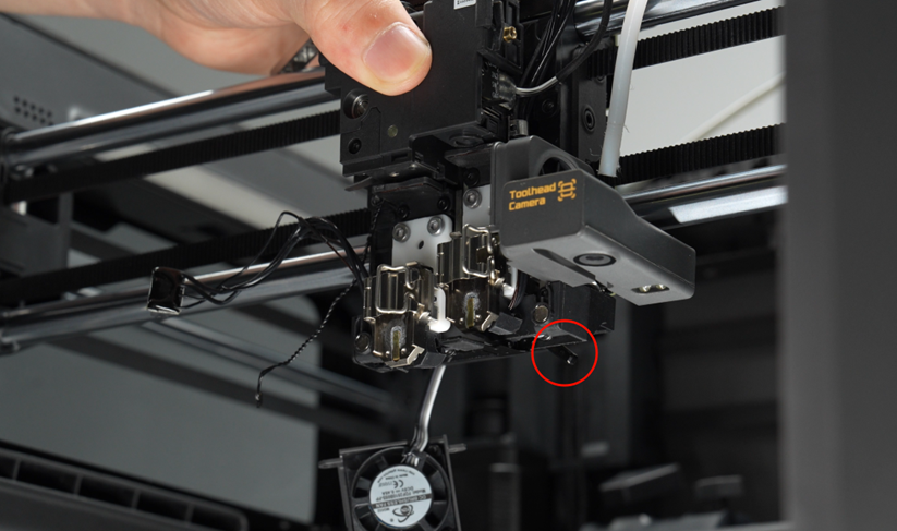
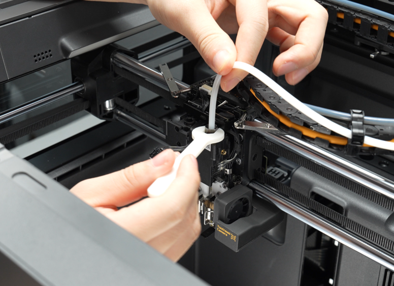
Install the left extruder PTFE tube onto the left pneumatic connector.
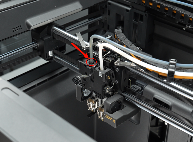
After installation, gently pull up the PTFE tube to check that it is properly seated.
Step 9. Install the left and right filament cutter lever assemblies
Restore the right filament cutter lever to its original position and tighten one screw,
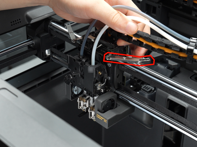
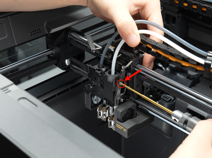
Restore the left filament cutter lever to its original position and tighten one screw,
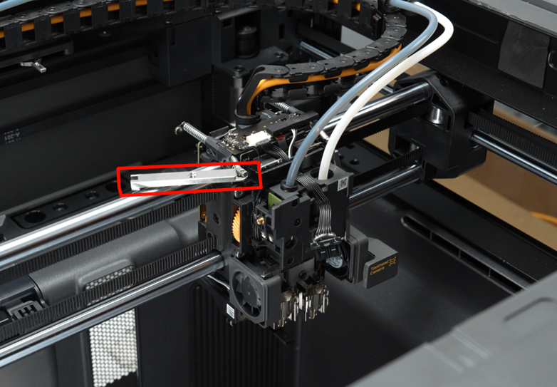
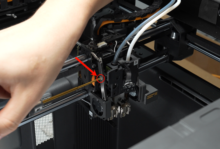
Note: The blades of the left and right cutter assemblies must be positioned within the slots of the filament cutter lever assemblies. Please refer to Filament Cutter Lever Replacement Guide for the X2D for a detailed tutorial on installing the filament cutter lever assemblies.
Step 10. Install the hotends
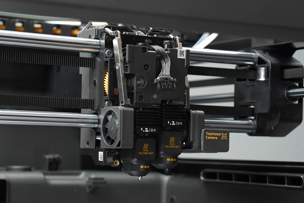
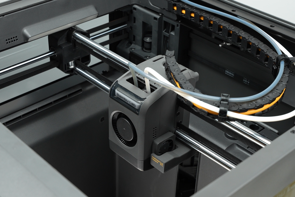
Step 11. Install the toolhead housing
Verifying Success
✅ The blade can move smoothly
✅ Power on and verify that the left and right filament sensor boards correctly detect filament status
✅ Power on and verify that the extruder is driven properly by the extruder motor