


Chamber Heater with APP for Bambu Lab P1 / X1
No se pudo cargar la disponibilidad para recoger
Utilice este texto para fomentar la comunicación o promover el intercambio en las redes sociales.
The chamber heater offers an additional chamber temperature heating APP control feature, with a max chamber temperature of 77℃. Higher chamber temperatures can reduce warping when printing high-temperature filaments and improve interlayer adhesion. Additionally, when printing with these high-temperature filaments, using the chamber heater can improve the print strength, particularly interlayer strength. For filaments such as PC, PA-CF, PAHT-CF, PET-CF, PPA-CF, PPS, and PPS-CF, setting the chamber temperature to 60°C can enhance dimensional accuracy and visual quality.
-
Maximum temperature: 80°C
-
The heater shell was printed with ABS-GF from Bambu Lab
-
Compatibility: for Bambu Lab X1, X1C, P1S, P1P; Voron Trident, (size NOT suitable for Voron 2.4); Creality K1, K1C, K1 Max, K2, K2 Plus 3D printers, etc.
-
Remote Control with APP: Sinilink
Warning: It is strongly recommended not to enable high chamber temperature when printing PLA, PETG, TPU, PVA and other low-temperature filaments. Enabling high chamber temperature may cause these filaments to soften and become lodged in the extruder, resulting in clogging issues.
Recommended chamber temp for various filaments
Chamber temp for PLA, PETG, TPU, PVA, PLA's supports and other low-temperature filaments: OFF
Chamber temp for ASA, ABS: OFF
Chamber temp for PC, PA, PA-CF, PAHT-CF, PA6-CF, PET-CF, PPA-CF, PPA-GF, PPS, PPS-CF and other high-temperature filaments: 60 ℃
Specifications:
Maximum temperature: 80°C
Size: 21x12x5cm
The heater shell was printed with ABS-GF from Bambu Lab
Rated Voltage: 220V / 110V for Japan
Rated Power: 150W
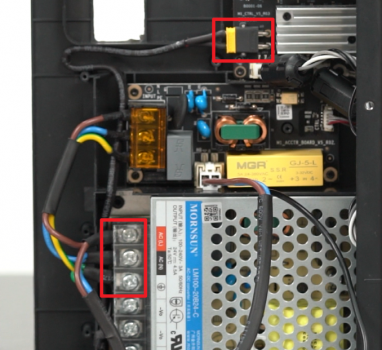
Chamber Heater Power:
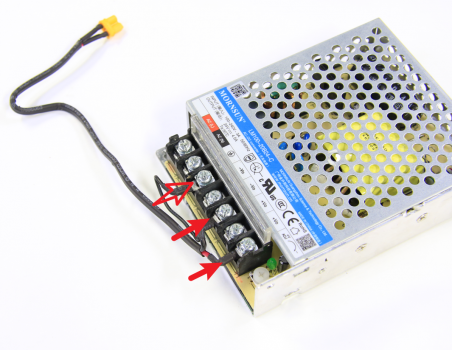
The power wires connected to the printer's power, to the AC L, and AC N.
For Bambu Lab X1 power supply info, you could refer to the Bambu La
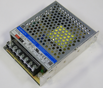
Replacing the power unit / 24V Power Supply
Guide for replacing the power unit / fanless 24V Power Supply
What is the power module
The power module is an AC to DC power converter, with variable input of 100-240V and output of 24V. It supplies power to the entire printer except the heatbed.
When to use
When you are certain the power supply is not operating, or components on the power module board are burnt.
Tools and materials needed
New power module
H1.5 & H2.0 allen key
phillips screwdriver.
Safety warning and Machine state before starting operation
Turn the power OFF and disconnect the power cord from the power socket.
Disassembly Guide
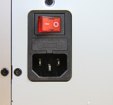
Step 1 - Disconnect the power cord
Disconnect the power cord from the power socket.
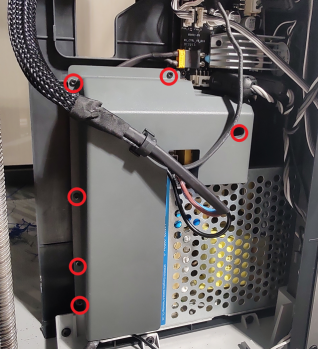
Step 2 - Remove screws
NOTE: There are a lot of screws involved in this procedure. Please label them and group them in separate sections as to avoid issues.
Remove the 10 screws and 4 screws from the rear cover shown in the picture. There are 2 types of screws, so keep them separate and remember which ones go where.

Step 3 - Remove rear cover
Remove the rear cover, unlock the left side belt tension ports first and then the right side one, to avoid getting stuck.

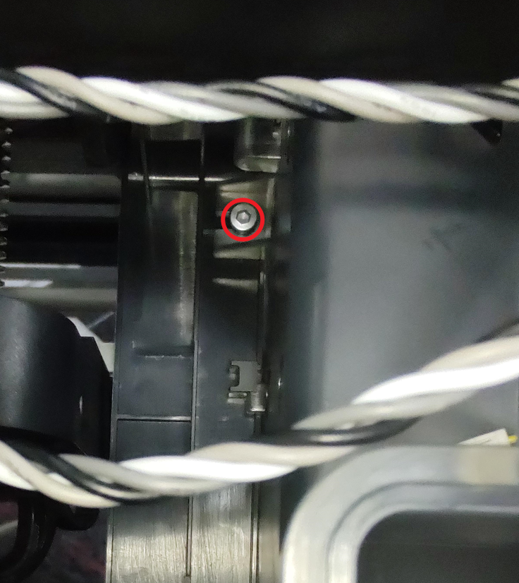
Note: Our newer printers feature an additional screw on the left side of the purge chute, which can be removed using an H2.0 Allen key.
Step 5 - Remove the protect cover
Remove 6 screws, move power module protect cover to the side and disconnect the power cable of the heatbed.

Step 6 - Disconnect cables
Open the interface cover,loose the 3 screws to remove the 3 cables, and the disconnect the power cable to MC board.
Step 7 - Remove the power module
Remove 2 screws, and then remove the power module.

Step 8 - Disconnect MC board power cable
Loosen the 2 screws shown, and then remove the MC board power cable.

Step 9 - (Assembly) Connect the MC board power cable
Connect the MC board power cable to the power board module, lock 2 screws (1 screw keep loose).
Assembly Guide
Step 1 - Install the power board
Install the power board module to the inner shield, lock in 2 screws (1 screw with ground cable).

Step 2 - Connect cables
Connect the 3 cables, close the interface cover , and connect the power cable to the connector on MC board. Connect the power cable of the heatbed.

Step 3 - Install the protect cover
Install the power module protect cover, and lock in 6 screws.
Step 4 - Install the purge chute
Install the purge chute, pay attention to the buckles on the both side, lock in 2 (or 3) screws.

Step 5 - Install the rear cover
Pass through the tube bracket and the right side belt tension port first to install rear cover.

Step 6 - Lock screws
Screw the back panel back on. Take note of the different types of screws used (10 and 4 as shown below).

How to verify completion/success
Connect the power cord and turn power ON. Operate the LCD screen and start a self-test. If no errors occur, the replacement is complete and successful.

Otherwise, check all the connections and try it again. If problems still persist, contact the Bambu Lab service team for further assistance.