

BirdsEye Camera for Bambu H3C
No se pudo cargar la disponibilidad para recoger
Utilice este texto para fomentar la comunicación o promover el intercambio en las redes sociales.
The BirdsEye Camera is a top-view camera used to photograph the work area from above for position alignment. It is optional for the cutting and drawing functions.
When not equipped with a BirdsEye Camera, you cannot directly take photos for alignment in Bambu Suite, but you can use Bambu Handy to complete the alignment by taking photos. For a smoother Crafting workflow, it is recommended to purchase a BirdsEye Camera.
In the Box
- BirdsEye Camera *1
- Adapter cable *1
- Cable clip *1
- AP board cable clip *1
- BT2x8 screw *1
- ST2.3x7 screw *1
BirdsEye Camera Replacement Guide for H3C
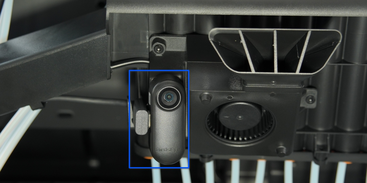
BirdsEye Camera
1.An optional 8-megapixel high-definition BirdsEye Camera is available. It supports two modes: In 3D printing monitoring mode, the resolution is 1632 × 1224 (30fps), ensuring smooth footage; in 2D overhead photography creation mode, the resolution can reach 3264 × 2448 (10fps), meeting high-accuracy shooting requirements.
Privacy tip: Please ensure the camera is correctly installed so that the camera field of view is correctly pointing towards the printer's chamber, to avoid any detection issues of the build plate or nozzles.
Filament Clip Installation Tips
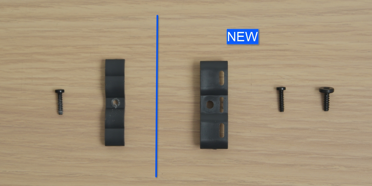
1.Accessory Replacement: A new filament retainer clip is included in the package. If the original clip is worn or damaged, replace it promptly; if it is in good condition, you can continue to reuse the original clip.
2.Screw Selection: There are 2 types of screws for the retainer clips on the market. The accessory package includes 2 corresponding spare screws. Be sure to use original screws of the same specification for fastening (e.g., if the original machine used thin and long screws, use the same type of thin and long screws for replacement) to ensure a secure installation.
When to Replace
Abnormal BirdsEye Camera image;
BirdsEye Camera communication failure.
Tools and Materials
H2.0 Allen key
H1.5 Allen Key
Safety Tips
Before performing any maintenance on the printer and its electronic components (including the toolhead cable), turn off the printer and disconnect the power supply to prevent accidental Screen touches or short circuits, which could cause additional electronic damage and safety hazards.
When performing maintenance or troubleshooting on your printer, please first check the temperature of the hotend and heatbed. Avoid operating at high temperatures. If operating at high temperatures is unavoidable, wear insulated gloves to ensure safe and effective maintenance.
Warm Tip
Step 5 is the most challenging part of this guide. While organizing the cables in this step ensures a more secure and neater setup, you can also choose to skip it—simply route the cables toward the back to avoid the filament tubes and keep things looking tidy. This also eliminates the need to reroute cables during future AMS disassembly, greatly simplifying the process.
Installing the BirdsEye Camera
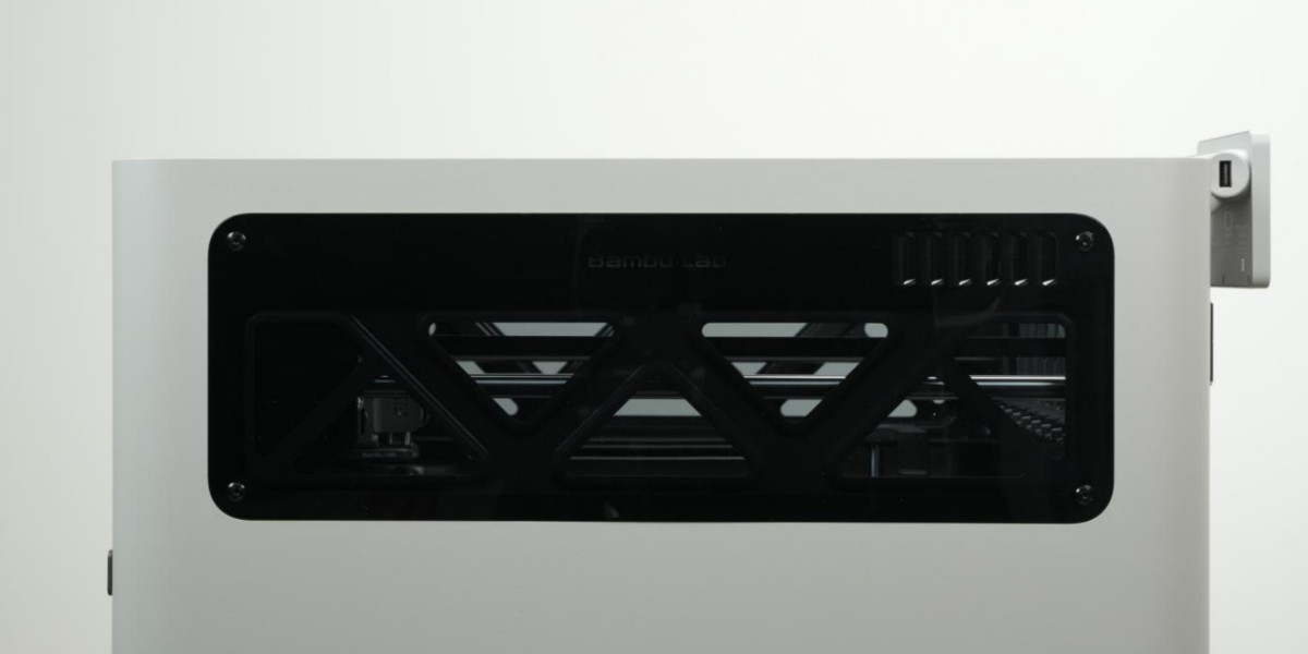
Step 1: Remove the AMS Left Magnetic Panel and Printer's Left Window

Caution: Never reach inside the XY (metal) frame via the viewing window while the machine is powered on, to avoid being pinched.
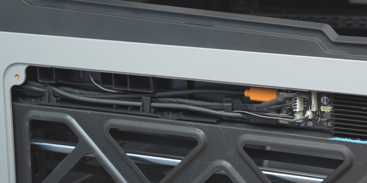
Step 2: Remove the Light Guide Plate and USB Cable Retainer
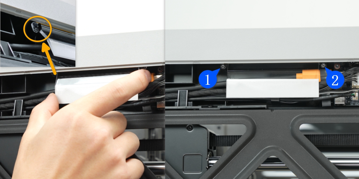
Depending on the printer version, if there is foam here, push it off to remove it.
Use an H1.5 Allen key to remove 2 screws and take out the light guide plate.
Note: You need to lift the light guide plate upwards, away from the locking tabs, before removing it.
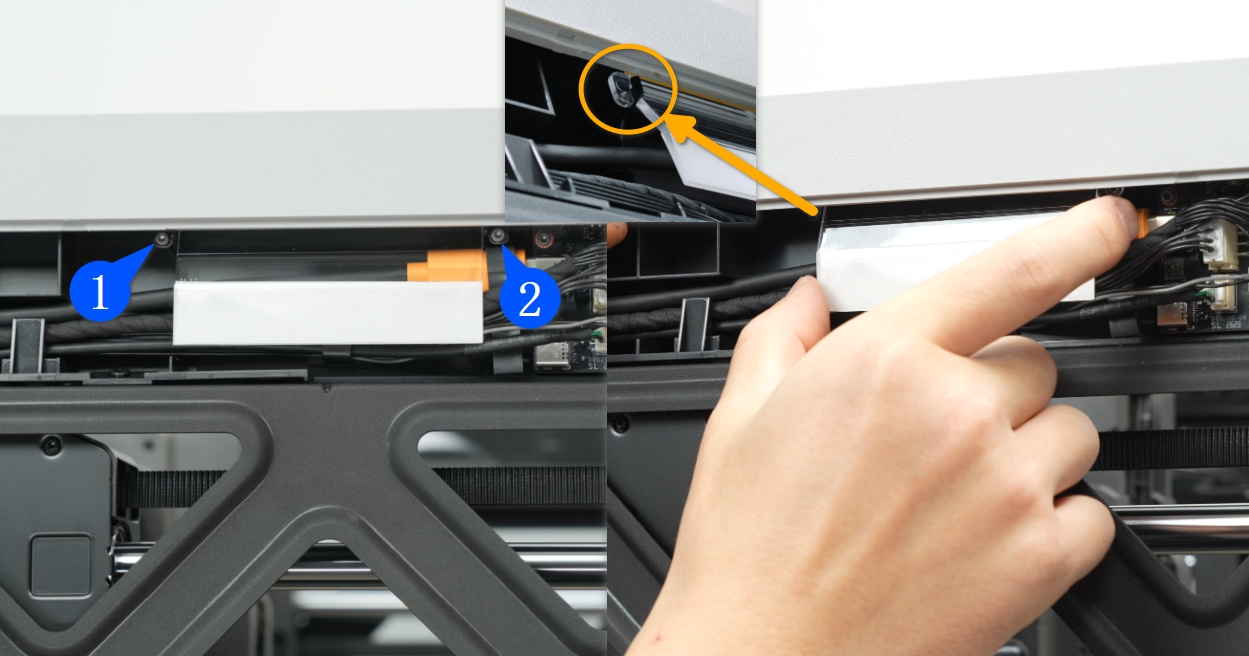
Use an H2.0 or H1.5 Allen key to remove 1 screw, and take off the USB cable retainer.
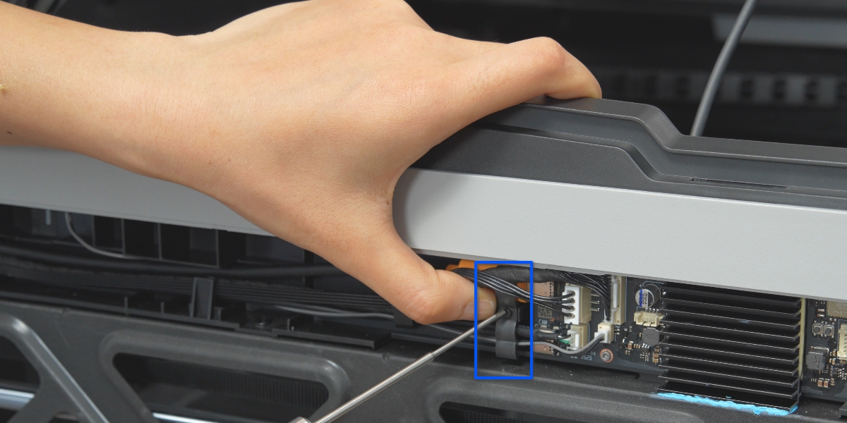
Step 3: Connect the BirdsEye Camera Cable
Use your hand or an Allen Key to locate the cable pass-through hole at the position circled in blue in the photo, and open it. Thread one end of the straight plug of the BirdsEye Camera cable through the reserved cable hole.

Organize the cable into the retainer clip and disconnect the two small connectors shown in the diagram on the AP board to create clearance.

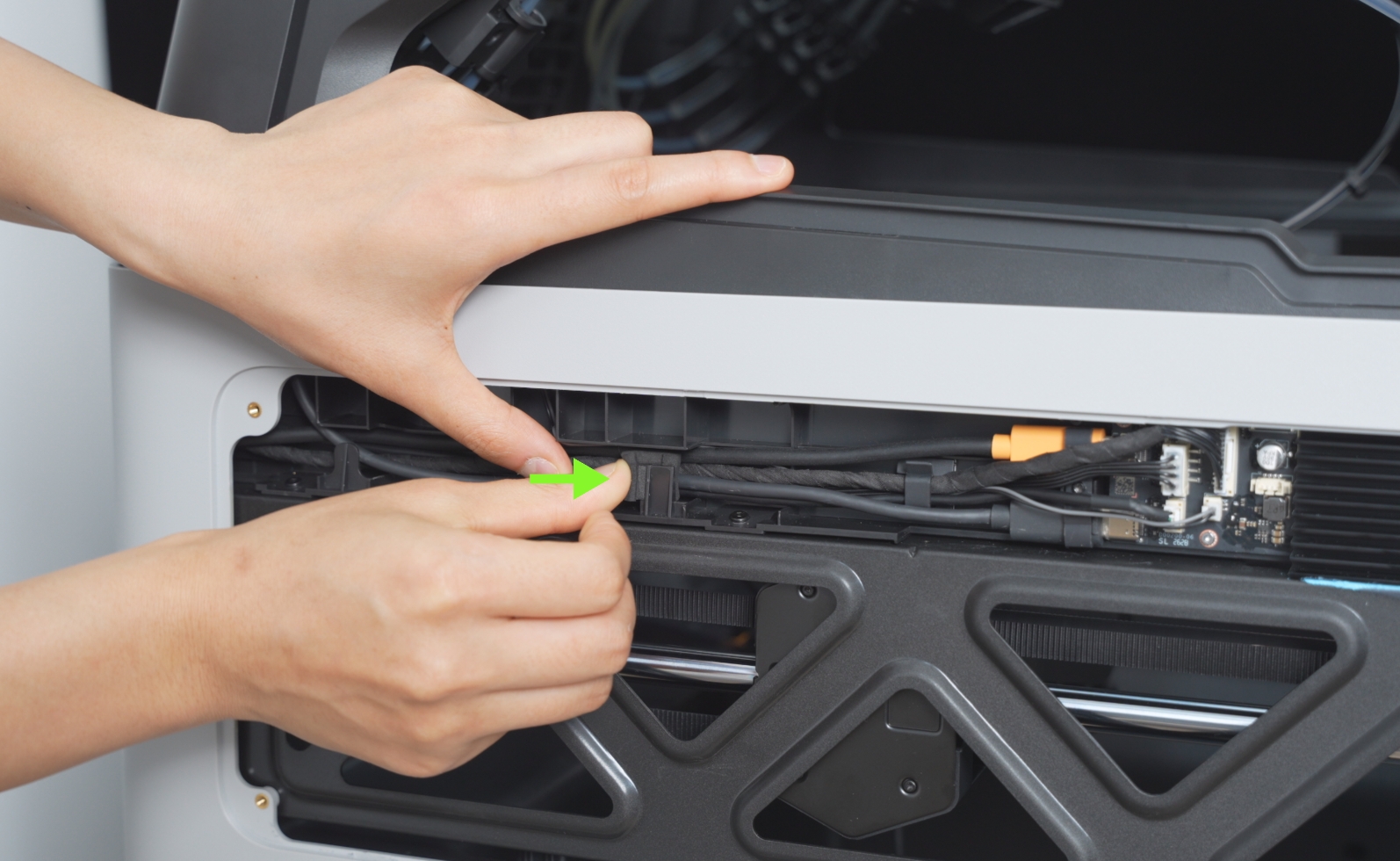
Check the orientation of the plug, with the raised side facing outward (extremely important), and then connect it to the USB port at the bottom left of the AP board.

Reconnect the 2 unplugged connectors; install the cable clips, press the two USB connectors firmly, and secure with 1 screw. Once the screw is tightened, please verify that all related plugs are firmly and correctly connected.

Step 4: Install the BirdsEye Camera
Thread the connector cable out from the space between the feed tube and bracket, ensuring smooth cable routing into the cable duct in Step 5. (Reminder: This ties into Step 5 cable management and can be done optionally.)

Connect the angled cable end to the camera, orienting it as shown in the diagram. The plug face must be facing the lens face directly (extremely important).

![]() When installing the BirdsEye Camera:
1.The camera's cable should snap into the AMS Supporting Frame's hook;
2.Align the claws at the bottom of the camera with the large notch on the AMS supporting frame mounting slot and insert it. Then, smoothly slide it towards the small notch until it clicks into place (Push backward from the front). Secure the camera.

Following the points above, align the camera's claws with the large notch on the AMS supporting frame and install it. Then, slide backward from the front to lock the camera. You should hear a click (extremely important) indicating it is properly installed.

Installation Status Confirmation (Extremely Important)
Please refer to the images below to confirm the correct installation of the camera into the bracket, ensuring it is fully seated.

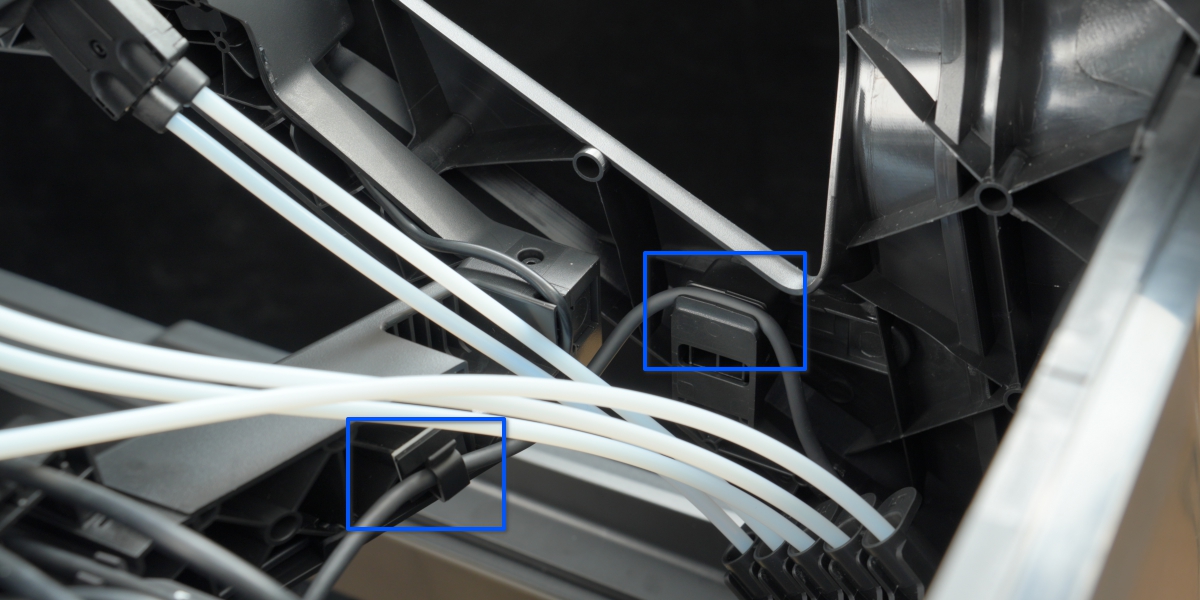
Step 5: Organize the BirdsEye camera cable (Optional, 3 cable management points - locking tabs or slots)
Tips: Step 5 is the most challenging part of this guide. While organizing the cables ensures a more secure and neater setup, you can also choose to skip this step—simply route the cables toward the back to avoid the filament tubes and keep things looking tidy. This also eliminates the need to reroute cables during future AMS disassembly, greatly simplifying the process.
Once you have more operating space, there is no need to remove the left filament tube bracket, simply route the cables into the two cable slots and tidy them up.
Reach into the cavity from the side of the AMS. Attach a cable clip (if available) to the left side of the main spool holder, press and hold for 5-8 seconds, with the opening facing upwards, and then clip the cable into the cable clip.

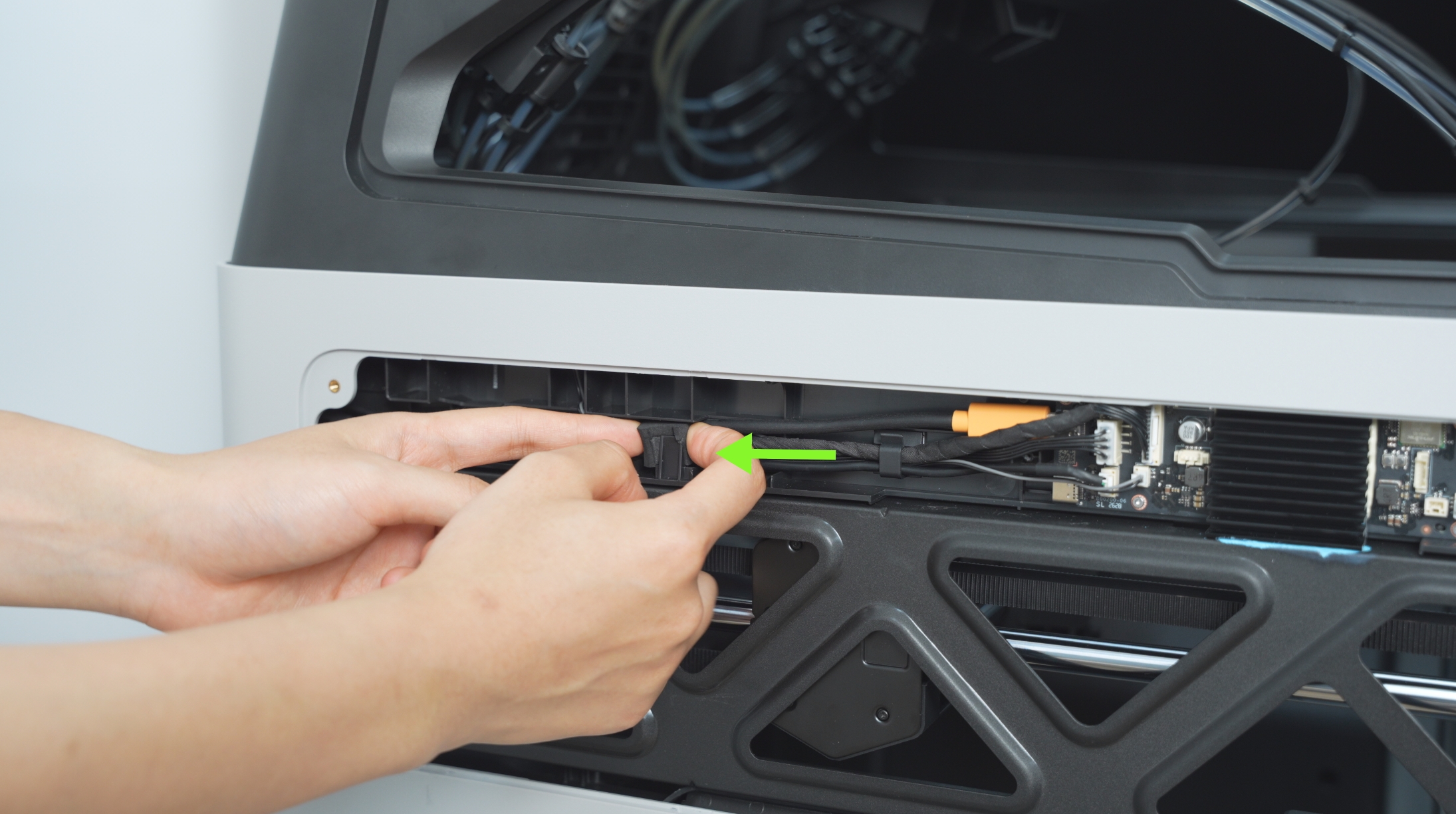
Reach into the cavity from the left side of the AMS. Place your thumb on the bottom edge of the bracket (part 1) and your index finger on the cable slot on the bracket (part 2). Pull out the left filament tube bracket.

Route the cable into the 2 cable slots on the upper-left filament tube bracket. Then, reinstall the left filament tube bracket and press it firmly into place.

Step 6: Install the Light Guide Plate and Window
Push the foam back into place (if applicable).
Align the light guide plate with the 2 screw holes. First, hook the screw positions on both sides of the light guide plate into the locking tabs, then secure it with 2 screws.
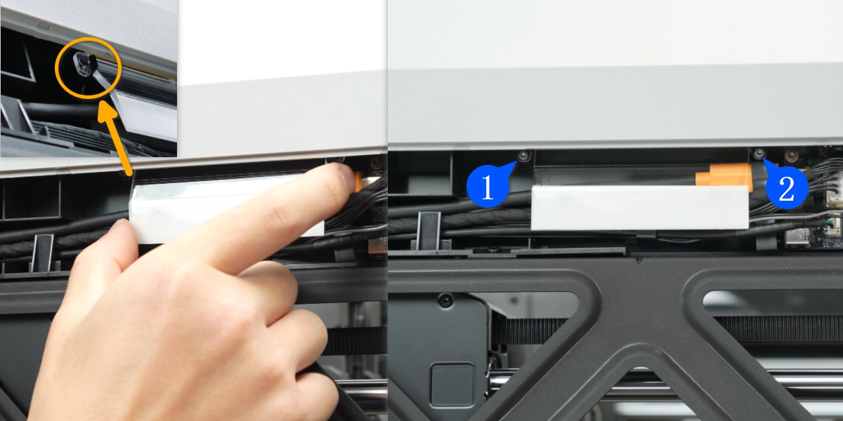
(You can install this after confirming the camera installation is successful)
How to Remove the BirdsEye Camera
Step 1: Remove the Window and Light Guide Plate
Refer to Steps 1 and 2 in this guide for installing the BirdsEye camera component, removing the window, light guide plate, and USB cable clip.
Step 2: Disconnect the BirdsEye Camera from the AP Board
Pull the USB connector backward to disconnect the cable from the AP board. Then, release the cable from the locking clip.

Pull the cable upwards through the guide hole. As you pull out the USB plug, use your hand to assist in adjusting the position and provide support.

Step 3: Remove the BirdsEye Camera
As shown in the image, slide the camera upwards to unlock the locking tab, then remove the camera from the AMS bracket.

Following the cable's routing path, loosen the cable and remove the BirdsEye camera.
Step 4: Install the Light Guide Plate, Window, and AMS Magnetic Side Panel
Push the foam back into place (if applicable).
Align the light guide plate with the 2 screw holes. First, hook the screw positions on both sides of the light guide plate into the locking tabs, then secure it with 2 screws.
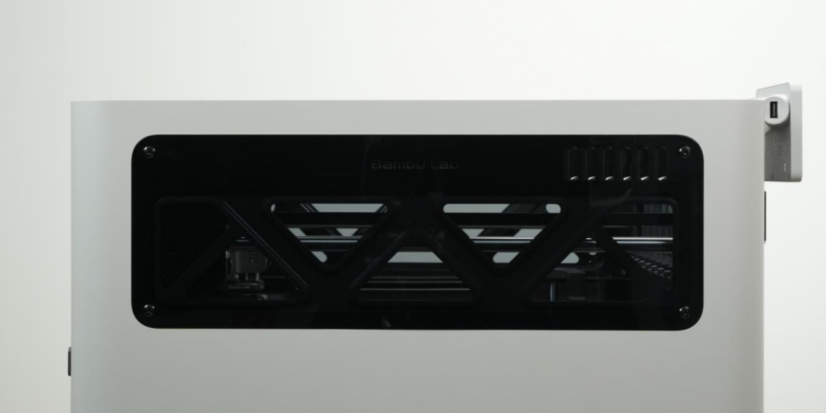
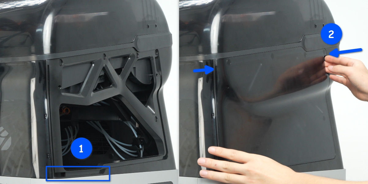
Align the mounting slots below the left/right frame, attach the left/right panel to the AMS Supporting Frame, and press the left/right panel to ensure it is fully seated without any lift.
Verify Functionality
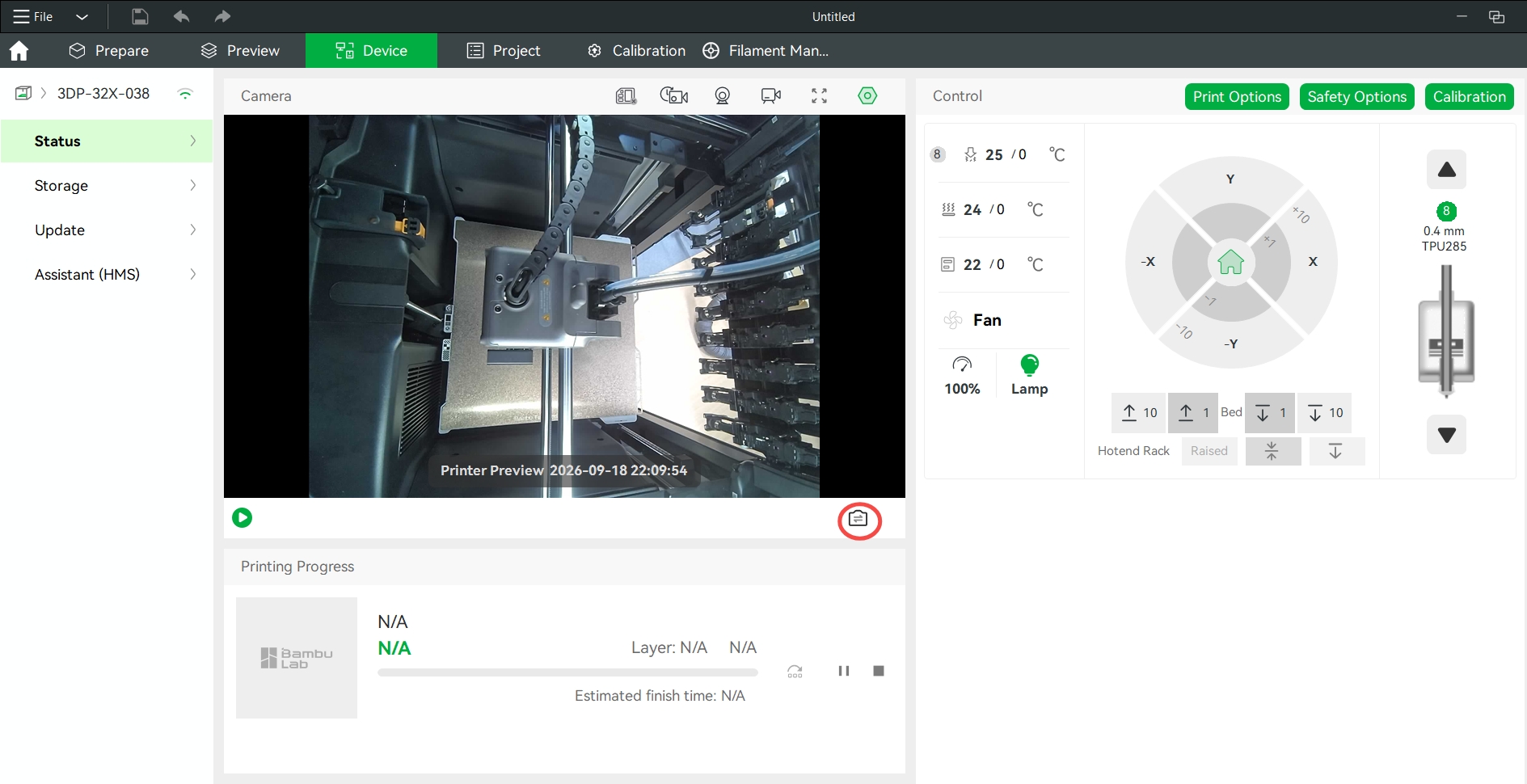
Power on and bind the printer via Bambu Studio. On the device status page, click the circled view-switch icon to switch to the BirdsEye view; if the feed displays normally, the installation is successful.