


Bambu X2D Toolhead Middle Housing / Front Cover / Rear Cover
No se pudo cargar la disponibilidad para recoger
Utilice este texto para fomentar la comunicación o promover el intercambio en las redes sociales.
Toolhead Middle Housing
A plastic enclosure designed to seal the middle part of the toolhead.
In the Box
- Toolhead Middle Frame *1
-BT2x5 Screw *4
Compatibility
X2D

Toolhead Front Cover Assembly
Includes the front cover housing and part-cooling fan, secured to the Toolhead Middle Housing via magnets.
In the Box
- Toolhead Front Cover Assembly *1
Compatibility
X2D

Toolhead Rear Cover
A plastic enclosure designed to seal the rear part of the toolhead.
In the Box
- Toolhead Rear Cover *1
- Spring*1
-BT2x5 Screw *4
Compatibility
X2D

Toolhead Housing Replacement Guide for the X2D
This page introduces how to replace the X2D toolhead housing.
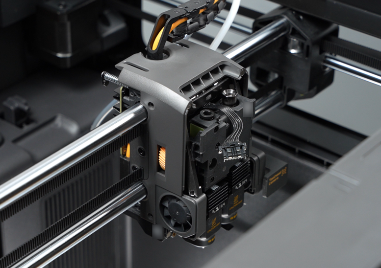
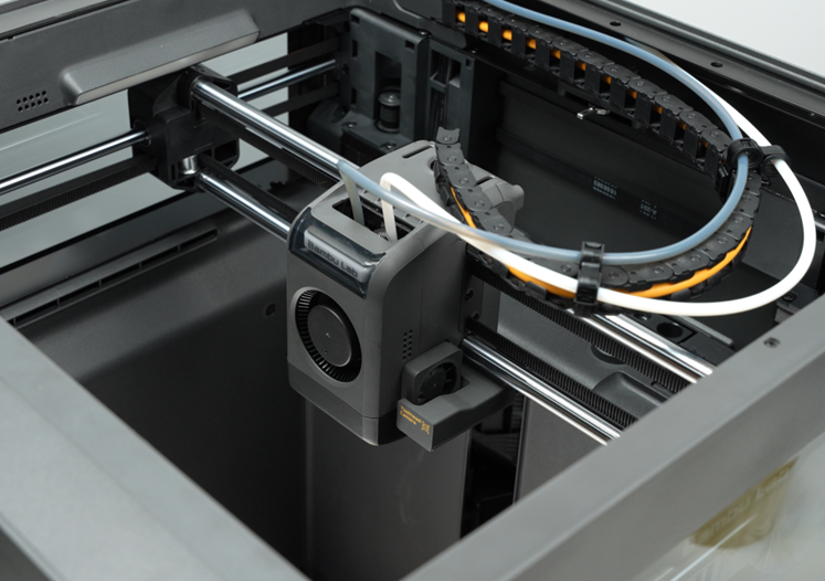
Toolhead Housing
🔎 Find the X2D Toolhead Housing in the Bambu Lab store.
The toolhead housing consists of 3 components:
1.Toolhead front cover assembly: composed of the toolhead front cover and Part Cooling Fan assembly, magnetically attached to the toolhead middle housing;
2.Toolhead rear cover: a plastic cover sealing the rear of the toolhead;
3.Toolhead middle housing assembly: a plastic cover at the center of the toolhead, with magnets on the upper part to secure the front cover assembly.

Applicable printer model
Bambu Lab X2D
When to Replace
Toolhead front cover assembly
Physical damage occurred, including magnet detachment
Part Cooling Fan failure
Toolhead rear cover
Physical damage occurred
Toolhead middle housing assembly
Physical damage occurred, including magnet detachment
Required tools and materials
H1.5 allen key
Wrench
Toolhead front cover assembly / toolhead rear cover / toolhead middle housing assembly
Safety Warning
⚠️ IMPORTANT!
It's crucial to power off the printer before conducting any maintenance work, including work on the printer's electronics and tool head wires. Performing tasks with the printer on can result in a short circuit, leading to electronic damage and safety hazards.
During maintenance or troubleshooting, you may need to disassemble parts, including the hotend. This exposes wires and electrical components that could short circuit if they contact each other, other metal, or electronic components while the printer is still on. This can result in damage to the printer's electronics and additional issues.
Therefore, it's crucial to turn off the printer and disconnect it from the power source before conducting any maintenance. This prevents short circuits or damage to the printer's electronics, ensuring safe and effective maintenance.
Remove the old toolhead housing
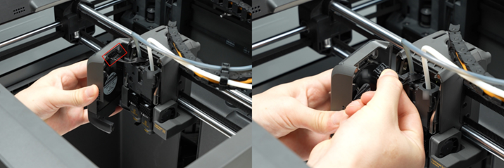
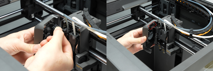
Step 1. Remove the toolhead front cover
Open the toolhead front cover, press the connector locking tab on the side to unplug the connector, and remove the toolhead front cover.
Step 2. Remove the toolhead rear coverUse an H1.5 allen key to remove the 4 screws on the side of the toolhead rear cover.
Use an H1.5 allen key to remove the 4 screws on the side of the toolhead rear cover.

Gently wiggle the toolhead rear cover to loosen the locking tabs (avoid excessive force to prevent tab breakage), then remove the toolhead rear cover.
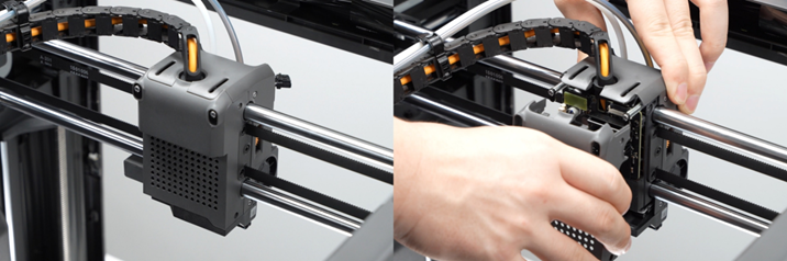
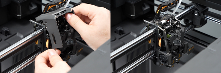
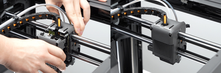
Step 3. Remove the toolhead middle housing
Use an H1.5 allen key to remove the 4 screws on the side.

ℹ️ Note: Removing the filament tubes below is not mandatory, but makes the middle housing easier to remove.If the maintenance does not involve the extruder or the extruder filament sensor board, the filament tubes can be left in place.
Press the pneumatic connector on the left extruder filament sensor board and unplug the filament tube.
Push the lever of the flow blocker assembly to the right to expose the pneumatic connector on the right extruder filament sensor board, then use a wrench to loosen the pneumatic connector counterclockwise and remove the filament tube.
Pry open the bottom of the middle housing by hand, loosen the left side first, then detach the toolhead middle housing from the Cable Chain bracket and remove it.
Install the new toolhead housing
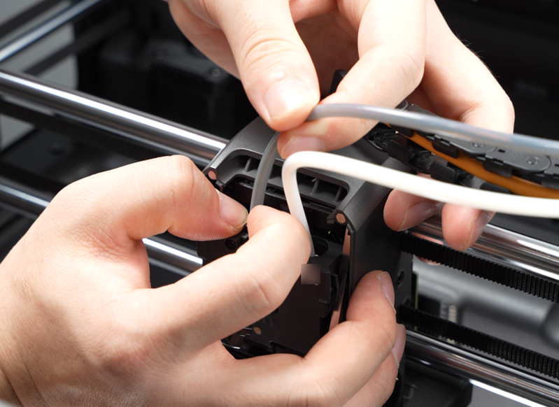
Step 1. Install the toolhead middle housing
Align the notch on the toolhead middle housing with the Cable Chain bracket and press in, avoiding interference with the toolhead camera on the right side.
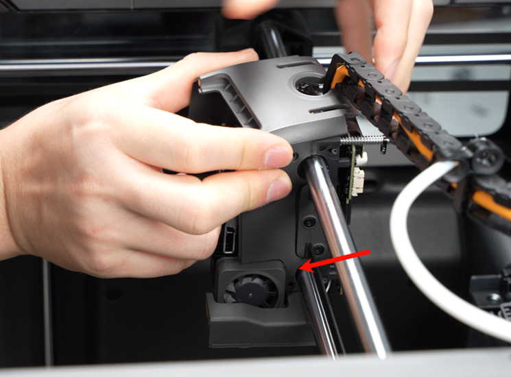
Install the middle housing onto the toolhead.
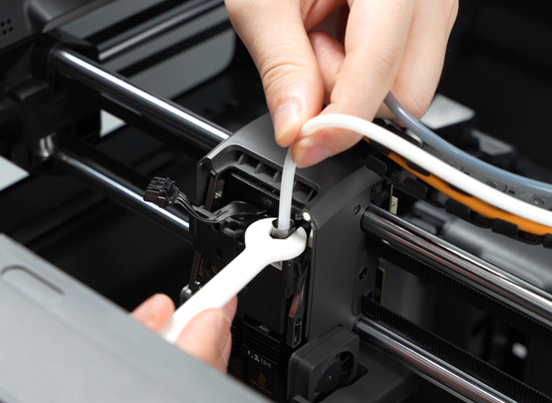
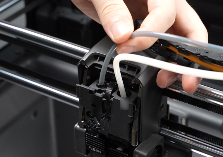
Install the filament tube of the auxiliary extruder onto the pneumatic connector, then use the printed wrench to tighten the pneumatic connector clockwise to secure the right filament tube.
Push the lever of the flow blocker assembly to the left to lower the pneumatic connector on the right extruder filament sensor board.

Install the left filament tube onto the left pneumatic connector and gently pull to check whether it is properly seated.
Tighten the 4 screws on the toolhead middle housing.
Step 2. Install the toolhead rear cover
Install the toolhead rear cover onto the toolhead, ensuring all locking tabs on the cover are properly engaged.
Then secure the 4 screws on the sides.
Step 3. Install the toolhead front cover assembly
Connect the toolhead front cover cable to the connector on the extruder connection board.
Organize the cables neatly and close the toolhead front cover assembly.
Verifying Success
✅ Check the gaps between housings for any obvious misalignment or lifting.
✅ The Part Cooling Fan operates normally, turning on and off as expected.