


Touch Screen for Bambu Lab-A1/A2L
Couldn't load pickup availability
Use this text to encourage communication or promote sharing on social networks.
Wide Compatibility: Designed for various 3D printer models, suitable for equipment upgrades, replacement parts and maintenance applications in home, workshop and professional printing environments.
Durable Material Structure: Made with reliable materials and precision manufacturing, featuring stable construction, accurate dimensions and convenient installation for long-term use.
Stable Printing Performance: Helps improve printer operation stability with consistent performance, smooth operation and reliable support for daily 3D printing tasks.
Multiple Application Scenarios: Suitable for 3D printing upgrades, repairs and customization projects, providing a practical solution for makers, engineers and printing enthusiasts.
Responsive Touch Interface - The sensitive touch panel enables intuitive navigation through printer menus, print file selection, and parameter adjustments, providing a smooth and efficient user interaction experience.
Straightforward Installation Process - Engineered as a direct drop-in replacement part, it allows users to complete the swap quickly using basic tools, restoring full control functionality without complex procedures.
3.5-inch IPS capacitive touchscreen which connects to the Mainboard which is used to control the printer through the touchscreen interface.
Compatibility
A1/A2L
In the Box
Touch Screen *1
Screen Replacement Guide - A1
This guide shows how to replace the Screen on the A1
In this guide we will show the process of replacing the Screen on the A1
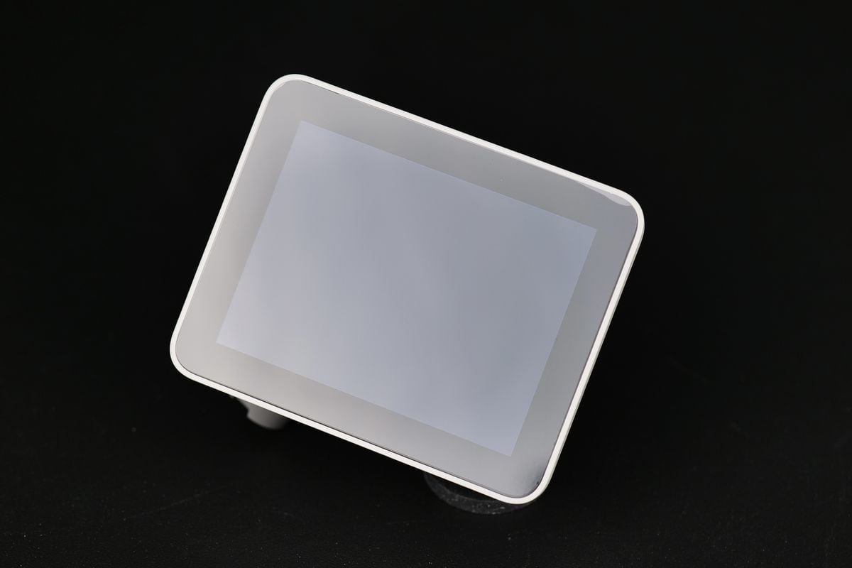
When to use?
This guide should be used if the Screen of the A1 is faulty, and needs to be replaced.
Common issues that are caused by the A1 Screen are:
Screen is not detecting any interaction
The screen is not turning on
Recommended by Bambu Lab Customer Support
Tools and materials needed
H2.0 Allen key
H1.5 Allen key
Flat end screwdriver or prying tool
Sharp pliers
20-30 minutes
Safety Warning
IMPORTANT!
It's crucial to power off the printer before performing any maintenance work on the printer and its electronics, including tool head wires, because leaving the printer on while conducting such tasks can cause a short circuit, which can lead to additional electronic damage and safety hazards.
When you perform maintenane or troubleshooting on the printer, you may be required to disassemble some parts, including the hotend. This process can expose wires and electrical components that could potentially short circuit if they come into contact with each other or with other metal or electronic components while the printer is still on. This can damage the electronics of the printer and cause further damage.
Therefore, it's essential to switch off the printer and disconnect it from the power source before doing any maintenance work. This will prevent any short circuits or damage to the printer's electronics. By doing so, you can avoid potential damage to the printer's electronic components and ensure that the maintenance work is performed safely and effectively.
Steps to remove the old screen
1. Place the printer on its front
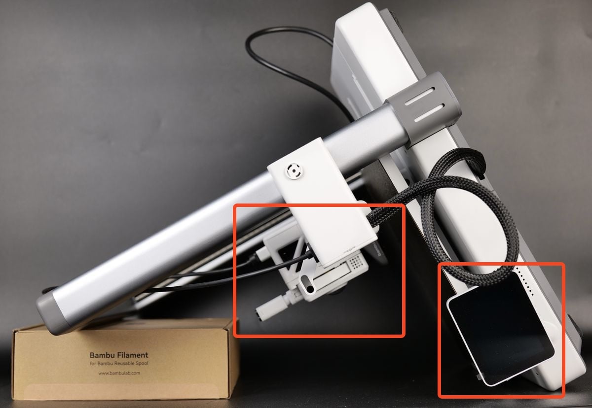
For easy access to the bottom section of the A1, you need to place the printer on the front.
Start by flipping the screen on its side, then gently place the printer on its front, as shown in the image below.
Use a box of filament to keep the top side raised to avoid putting pressure on the extruder and the screen.
2. Disconnect the wires and remove the wire bracket
1.Disconnect the cables of the camera, X-axis motor, and Z-axis motor;
2.Loosen 1 screw;
3.Push the cable bracket upwards, disconnect the USB data cable, and remove the cable bracket.
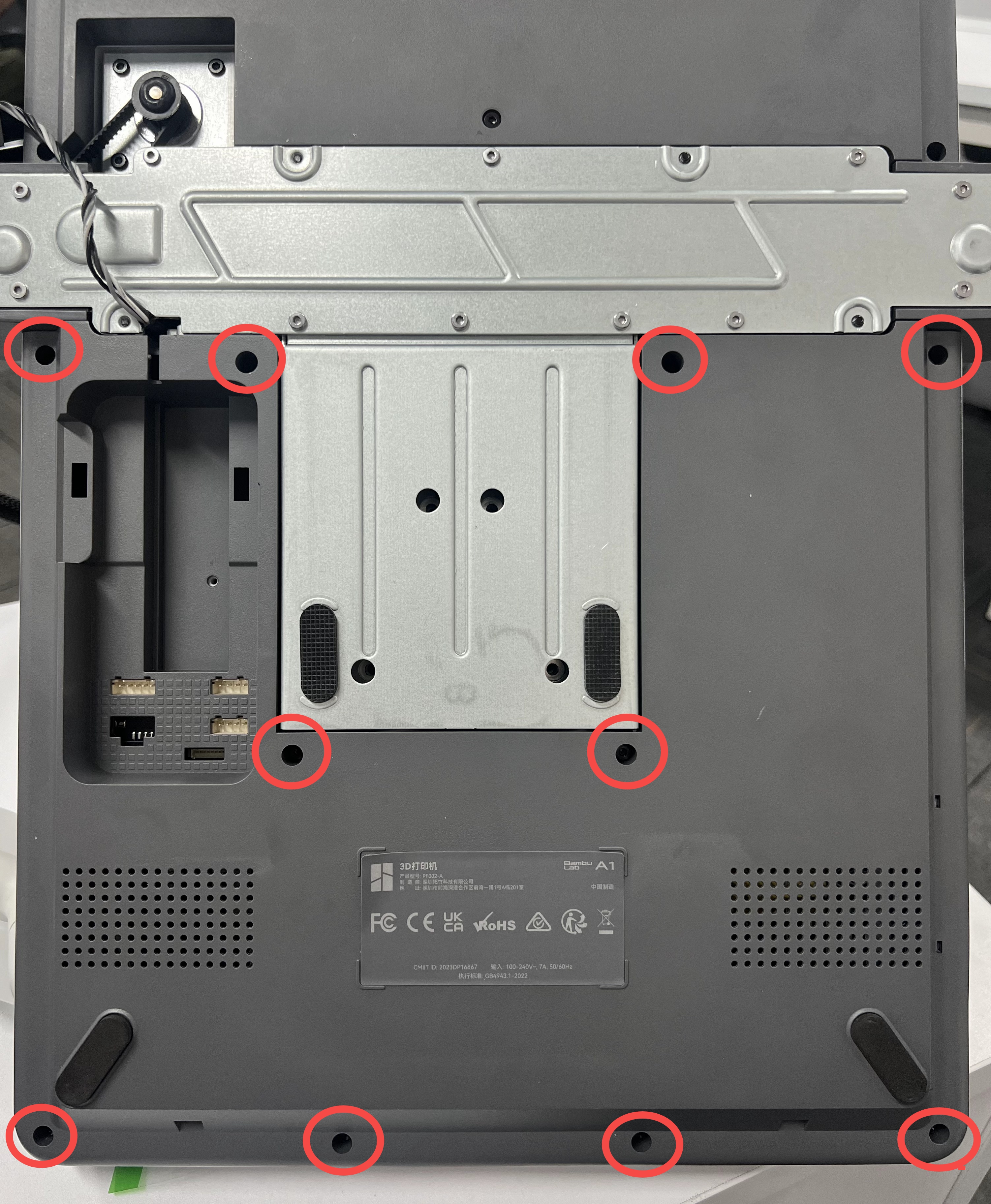
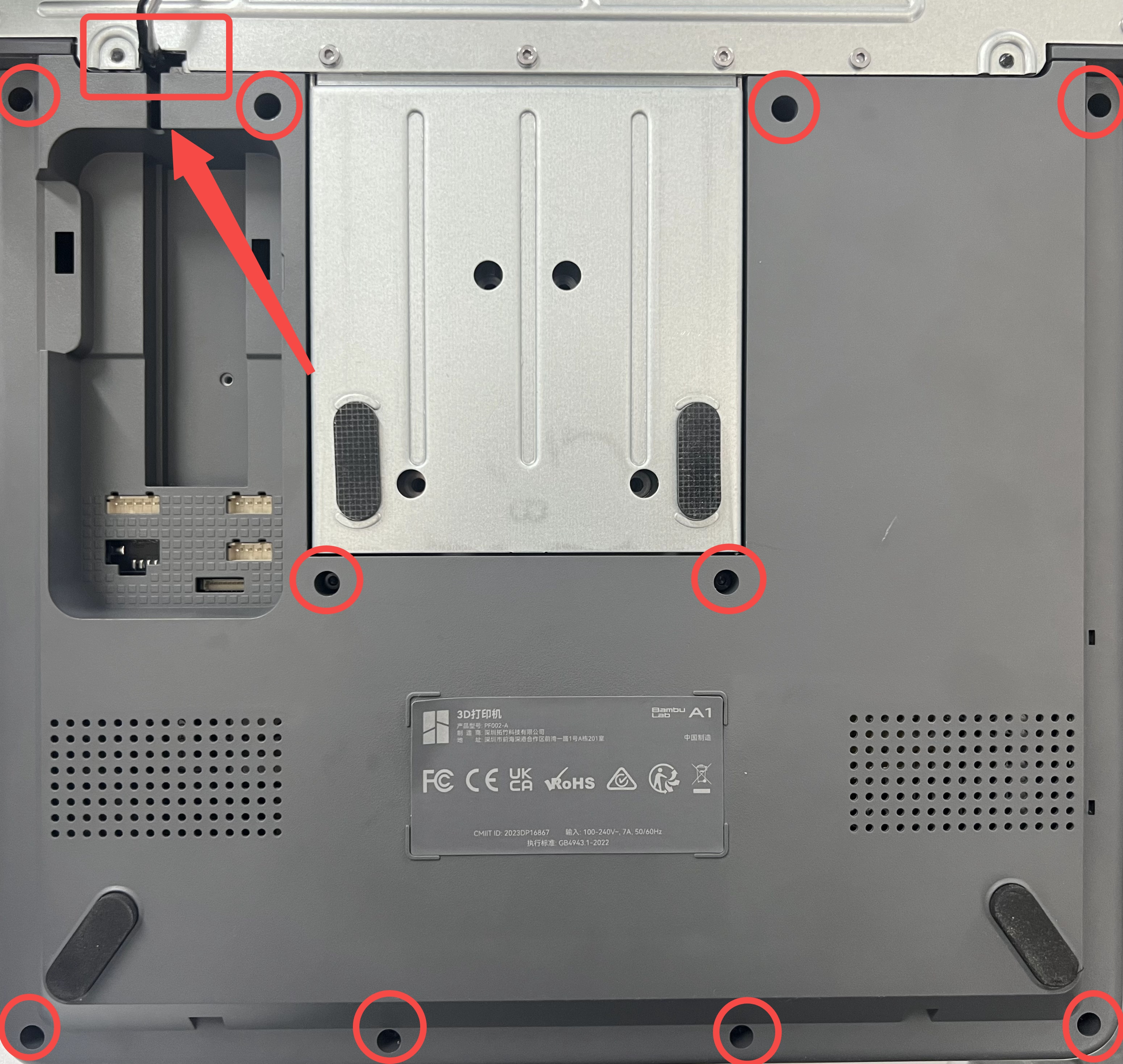
 3. Remove the printer's bottom cover
Remove the 10 screws marked in red to remove the bottom cover.
4. Disconnect the Screen ribbon cable
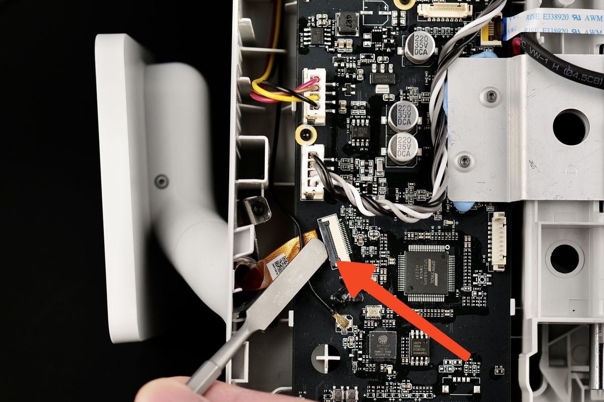
Carefully raise the black plastic clip from the Mainboard to release the ribbon cable of the screen.
When released, you can easily remove it from the board.
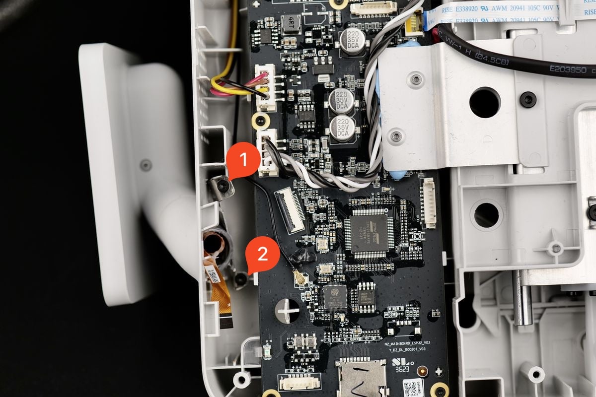
5. Remove the Screen clip
As shown in the image, remove the two screws holding the screen metallic clip in place.
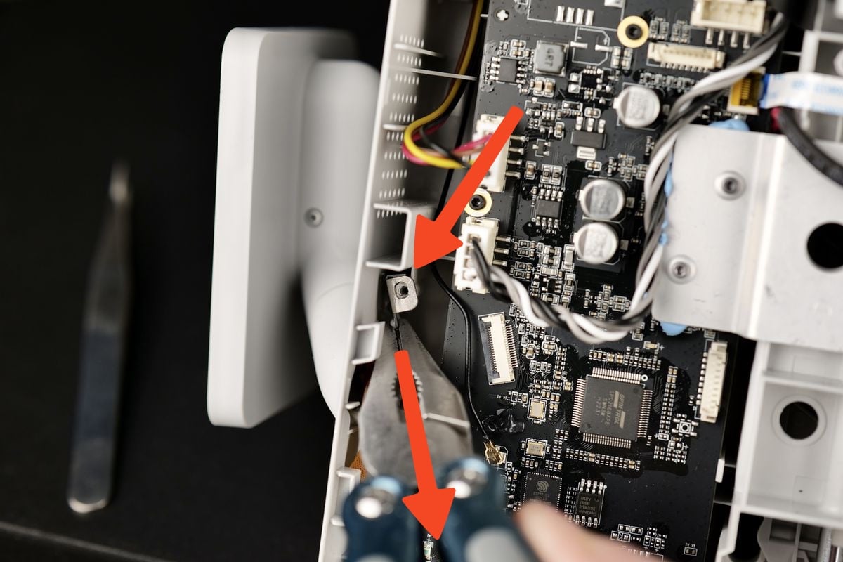
Next, grab the metallic clip with a pair of sharp pliers and pull it towards you. There will be some slight resistance, so pull it out carefully to avoid damaging the mainboard.
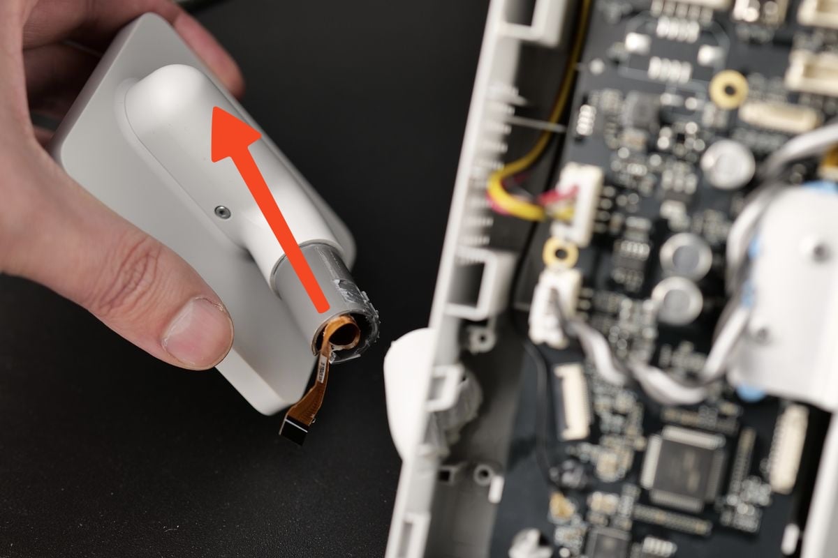
6. Remove the Screen from the printer
With the clip removed, you can now completely remove the screen from the printer.
Please take note of the angle shown in the picture. The screen has plastic tabs in its holder, and can only be removed when the plastic tabs are aligned.
Install the new Screen
1. Attach the Screen to the printer
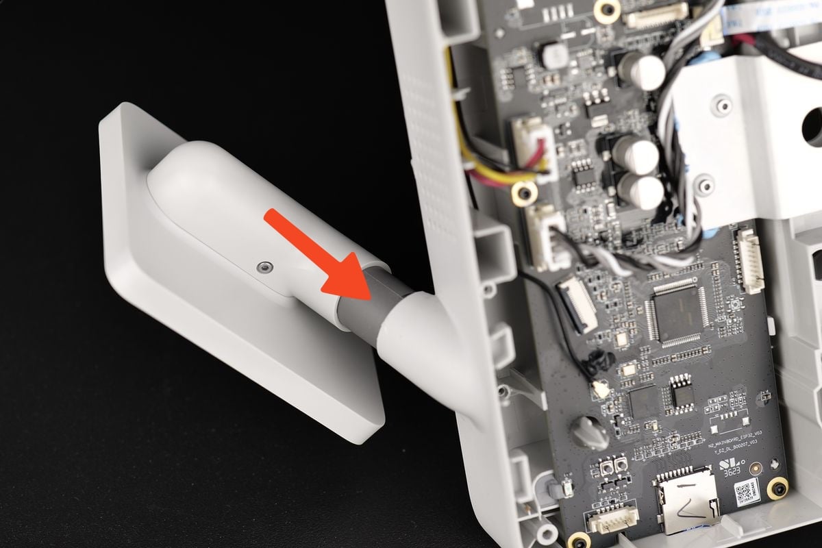
Carefully slide the screen through the hole, half way. This will make the next steps easier.
Please take note of the angle shown in the picture. The screen has plastic tabs in its holder, and can only be inserted when the plastic tabs are aligned.
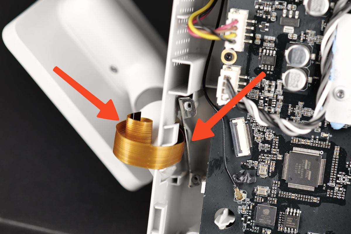
2. Install the metallic bracket
Carefully align the metallic bracket as shown in the image, while making sure that the ribbon cable is pulled to the side of the printer as shown in the image.
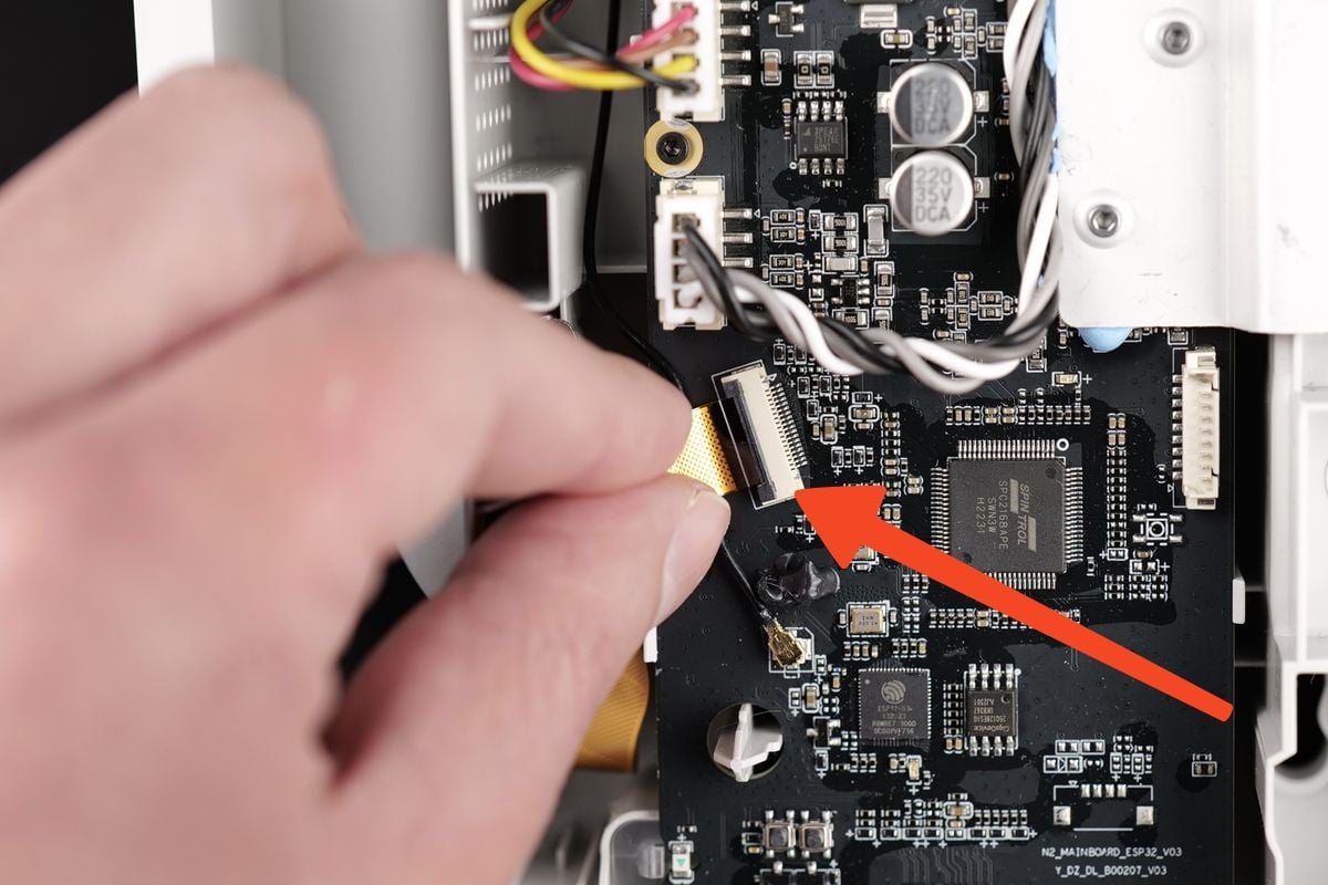
3. Attach the Screen ribbon cable
Gently push the ribbon cable in the motherboard connector, then lock the black plastic clip in place to secure it.
Ensure that the white line on the ribbon cable is aligned, as shown in the image below.
4. Install the the printer's bottom cover
You can now proceed with installing the bottom cover back to the printer.
Pay close attention to the motor wire in the top left side marked with the red arrow in the image below. Avoid pressing the cover in place before the wire is correctly managed.
The cover will clip in place, then you can proceed with installing the 10 screws while ensuring you do not over-tighten them.
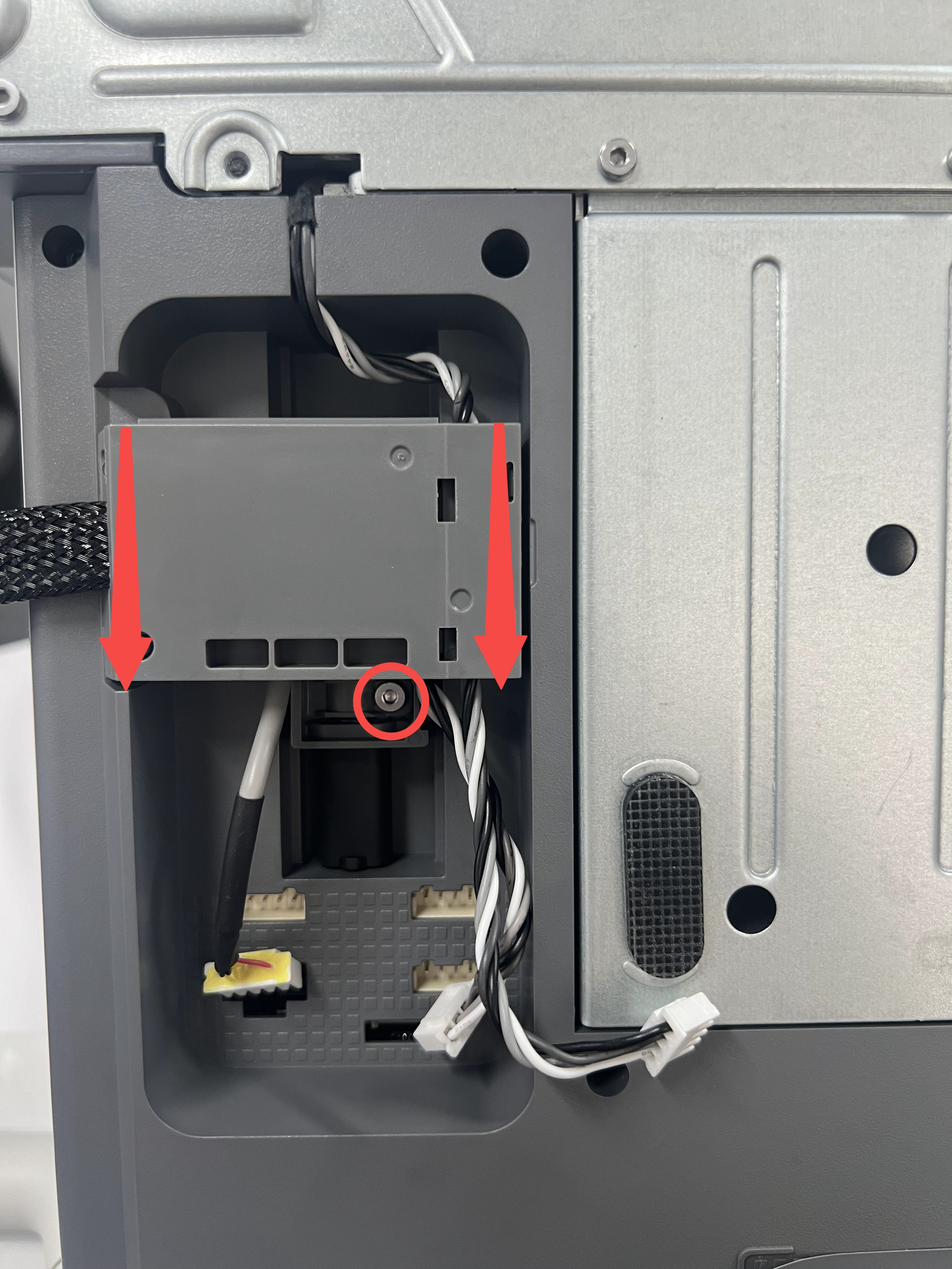
5. Install the wire bracket and connect the wires
In the final step, carefully align the wire bracket then push it downwards while making sure the USB cable is fully pushed against the printer frame.
Then, tighten the screw shown in the image to lock it in place. Avoid overtightening the screw as this is screwed into the plastic frame.
Next, re-connect the Camera, X-axis motor and Z-axis motor cables to finish the installation.
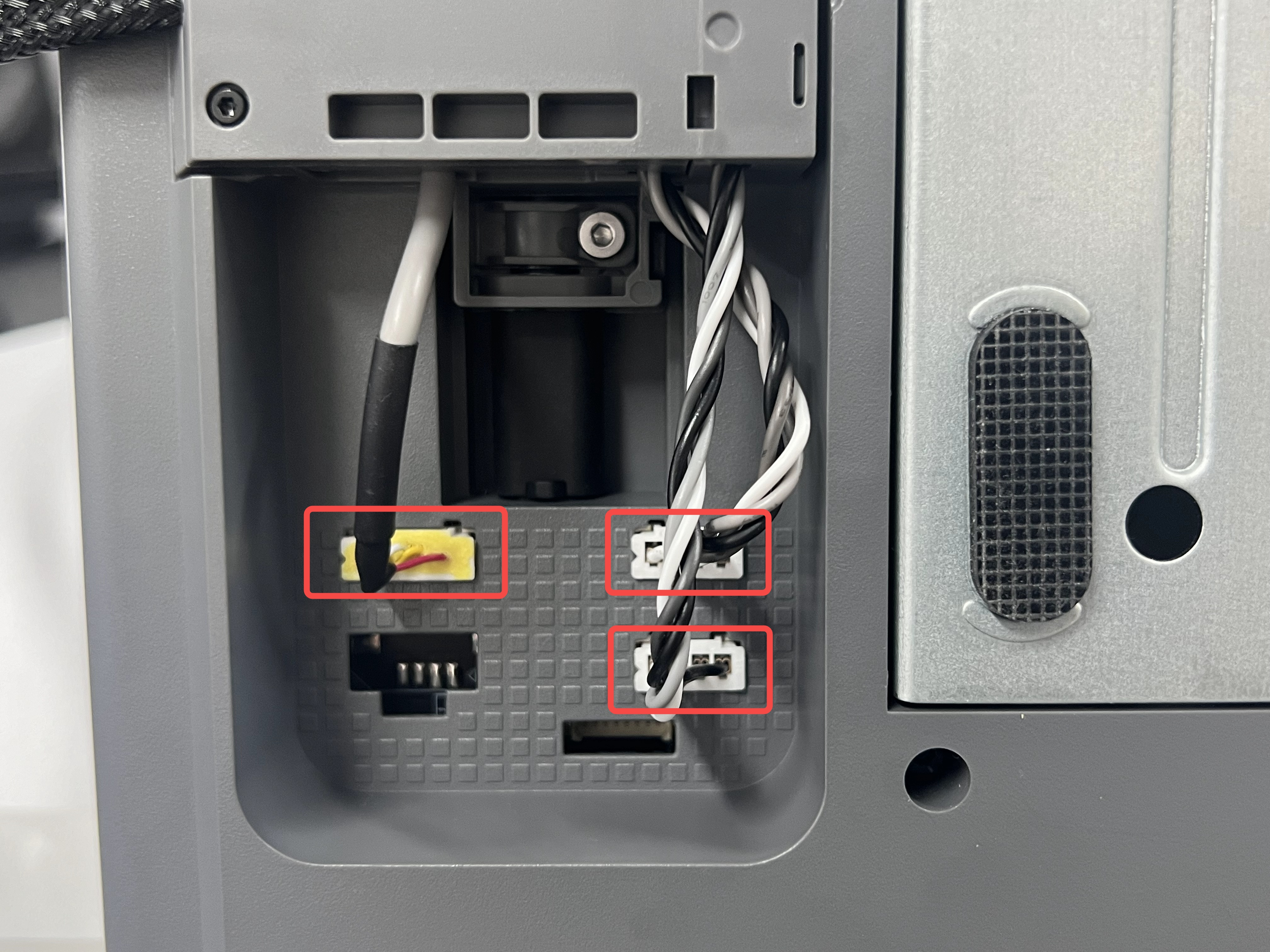
Note: The shorter cable on the right is the X-axis motor cable, which connects to the upper right connector; The longer cable on the right is the Z-axis motor cable, which connects to the lower right connector.
Verify the functionality
To ensure everything works as expected, turn on the printer and interact with the screen.
If the screen touch is detected, this confirms the installation was correct.
Potential problems and solutions
If you encounter problems during the installation of a new Screen, please check the potential problems and solutions listed below:
The Camera is not working
Confirm the camera wire is fully installed as shown in Step 5. Install the wire bracket and connect the wires
The X-axis / Z-axis is not working
Confirm the X motor and Z motor wires are fully installed as shown in Step 5. Install the wire bracket and connect the wires
The screen displays an error message
The USB cable might not be fully inserted. Loosen the screw holding the wire bracket in place, then re-connect the USB cable as shown in Step 5. Install the wire bracket and connect the wires
Screen not turning on / touch not detected
Confirm the ribbon cable is correctly installed, as shown in Step 3. Attach the Screen ribbon cable