


Bambu Lab P2S Toolhead Front Cover / Rear Cover / Middle Frame
Couldn't load pickup availability
Use this text to encourage communication or promote sharing on social networks.
Toolhead Housing Replacement Guide for the P2S
This guide demonstrates how to replace the toolhead housing of P2S.
Toolhead Housing
The Toolhead Housing consists of three main parts:
Toolhead Front Cover Assembly: Includes the front cover housing and part-cooling fan, secured to the Toolhead Middle Frame via magnets.
Toolhead Rear Cover: A plastic enclosure designed to seal the rear part of the toolhead.
Toolhead Middle Frame: A central plastic housing with magnets for front cover attachment.
Toolhead Front Cover
Physical damage, including magnet detachment.
Part-cooling fan malfunction.
Toolhead Rear Cover
Physical damage
Toolhead Middle Frame
Physical damage, including magnet detachment.
Required Tools and Materials
H1.5 Allen key
A new Toolhead Front Cover/Toolhead Rear Cover/Toolhead Middle Frame
Safety Warning
IMPORTANT!
Always power off and disconnect power on the printer before performing maintenance work. Not doing so means there is a risk of electric shock, short circuit, and damage to the printer or surrounding area.
When a maintenance task necessitates the printer being powered on, use insulated gloves for safety and pay special care not to pinch, damage, or put pressure on any exposed wires, connectors, or circuit boards. Additionally, the nozzle can be extremely hot so never touch it with exposed skin.
Removing the Toolhead Housing
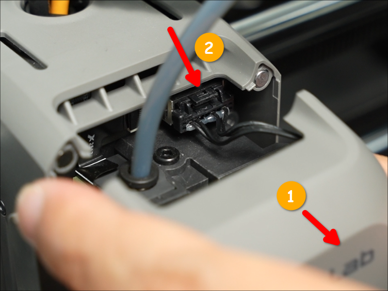
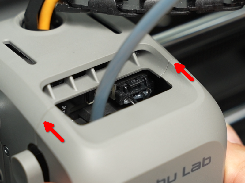
Step 1: Remove the Toolhead Front Cover
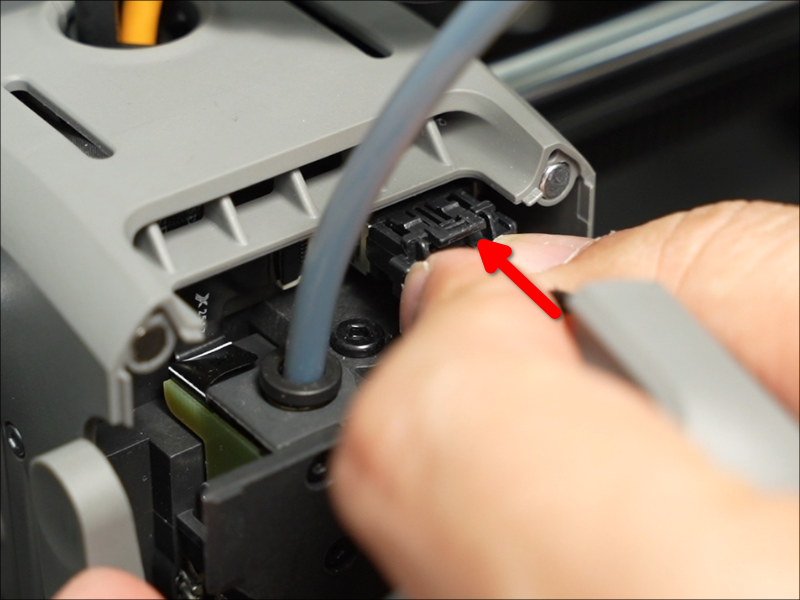
Open the Toolhead Front Cover, press the connector latch to unplug the cable, and then remove the Toolhead Front Cover.
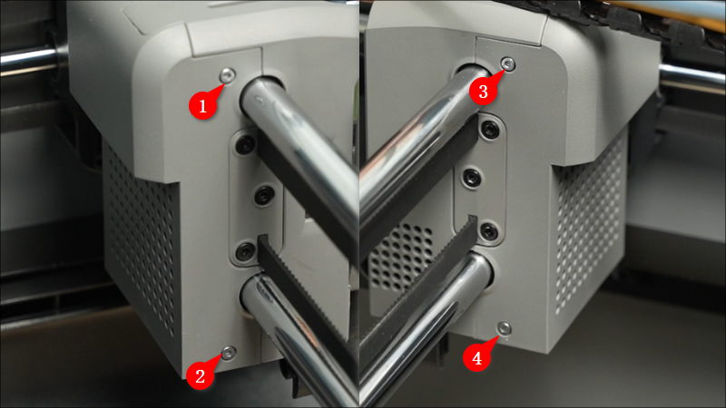
 Step 2: Remove the Toolhead Rear Cover
Remove the four screws with an H1.5 Allen key.
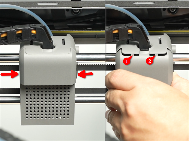
 Grip the Rear Cover near the upper rod, then pull it backward firmly to detach it.
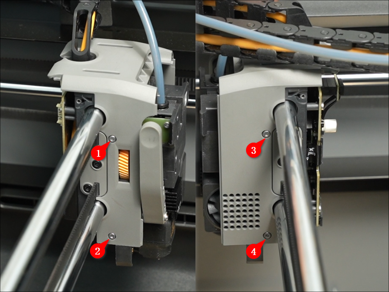
 Step 3: Remove the Toolhead Middle Frame
Remove the four screws with an H1.5 Allen key.
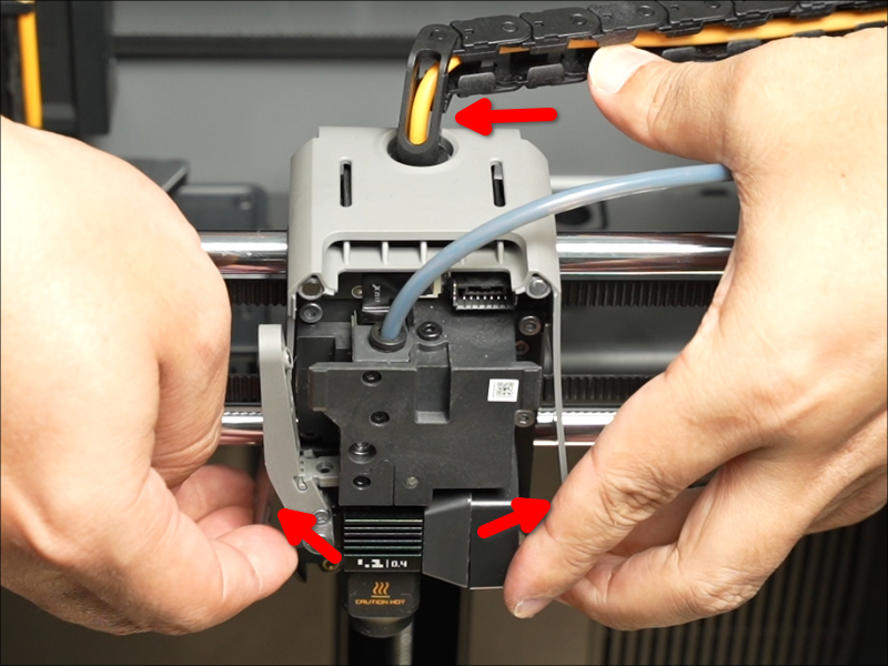
 Rotate the cable chain bracket to align it with the notch at the top of the Middle Frame, then gently lift the bottom of the Middle Frame upward to release it.
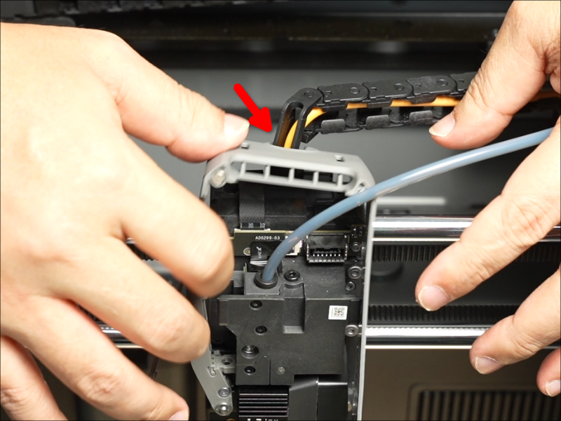
 Detach the Toolhead Middle Frame from the cable chain bracket, then remove it.
 Installing the Toolhead Housing
Step 1: Install the Toolhead Middle Frame
Align the notch on the Printhead Middle Frame with the cable chain bracket, then slide it into position.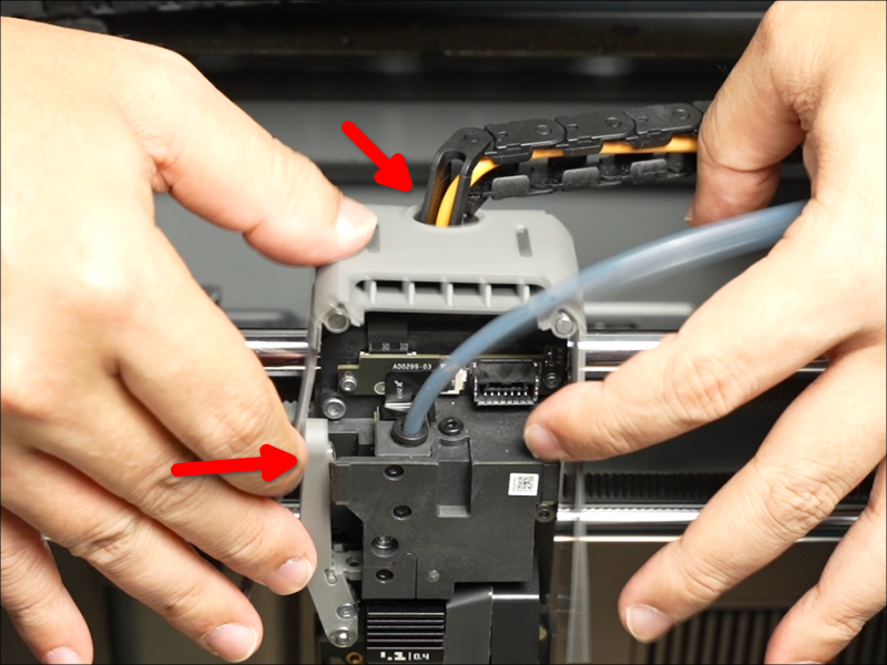 Install the Middle Frame and secure it with the four screws.
Step 2: Install the Toolhead Rear Cover
Install the Toolhead Rear Cover, then secure it with four screws.
 Step 3: Install the Toolhead Front Cover
Connect the Toolhead Front Cover cable to the Extruder Connection Board connector.
 The Toolhead Front Cover Assembly is magnetically secured. To reinstall, simply close it into position.
 Verifying Functionality
Check the gaps between the housing parts to ensure there is no visible misalignment or lifting.
Verify that the part-cooling fan turns on and off normally.