

Toolhead Front Carriage for Bambu-X1/P1 Series
Couldn't load pickup availability
Use this text to encourage communication or promote sharing on social networks.
Direct fit for Bambu Lab X1 / P1 series 3D printers. Aligns perfectly with original mounting holes for seamless replacement.
Firmly Secures Extruder Assembly Holds the extruder and filament cutter arm tightly to avoid loose parts even during high-speed printing, keeping your printer running stably.
High Heat-Resistant Engineering Plastic Constructed from robust heat-resistant plastic, it withstands continuous printing heat without deformation for long-term service life.
Reliable Internal Protection Shields the toolhead’s wiring, motor and sensors against dust, debris and accidental bumps to reduce component failure.
Tool-Free Quick Installation Precise cutouts and magnetic positioning support fast assembly and maintenance, no extra tools required.
Safety Warning
IMPORTANT!
It's crucial to power off the printer before conducting any maintenance work, including work on the printer's electronics and tool head wires. Performing tasks with the printer on can result in a short circuit, leading to electronic damage and safety hazards.
During maintenance or troubleshooting, you may need to disassemble parts, including the hotend. This exposes wires and electrical components that could short circuit if they contact each other, other metal, or electronic components while the printer is still on. This can result in damage to the printer's electronics and additional issues.
Therefore, it's crucial to turn off the printer and disconnect it from the power source before conducting any maintenance. This prevents short circuits or damage to the printer's electronics, ensuring safe and effective maintenance.
Operational guide
Step 1 - Remove the TH board assembly

Step 2 - Remove the LOGO LED cable
Remove the LOGO LED cable.

Step 3 - Remove the bambu micro lidar
Remove 2 screws with an H1.5 hex key and remove the micro lidar assembly.

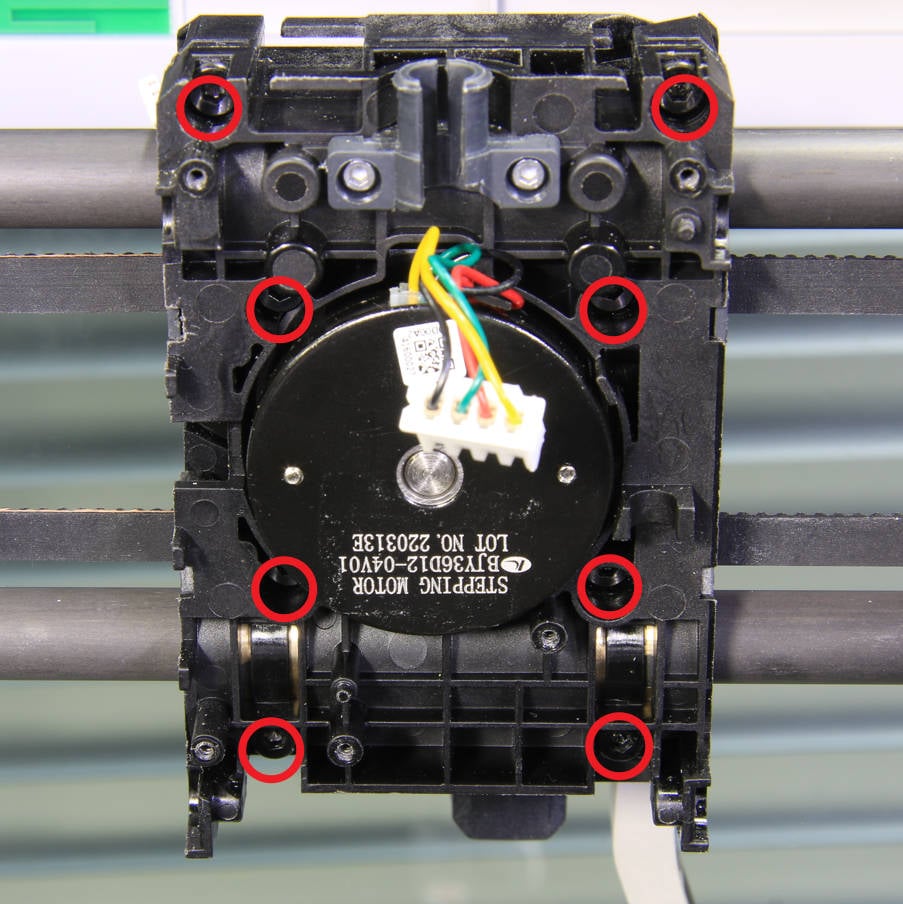
Step 4 - Remove 8 screws
Remove 8 screws with an H2.0 hex key in sequence.
Step 5 - Remove the Toolhead Front Carriage assembly of the toolhead slider
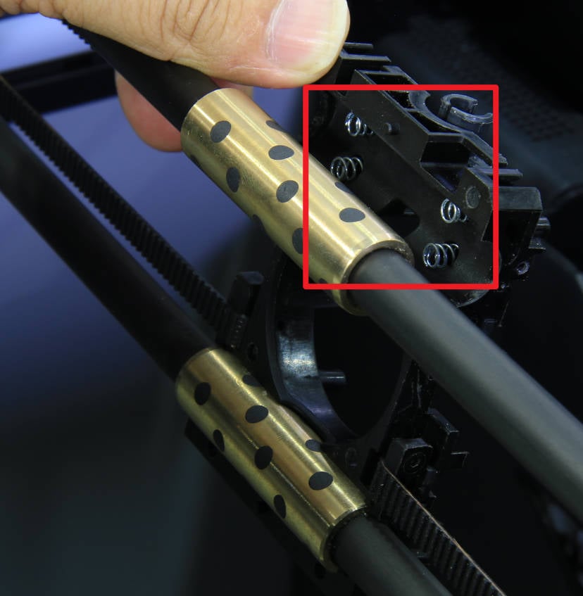
Remove the toolhead front carriage assembly (with the extruder) of the toolhead.

Note: There are four springs attached to the back cover of the tool head slider at the upper position of the copper sleeve to prevent it from falling off.
Step 6 - Remove the extruder
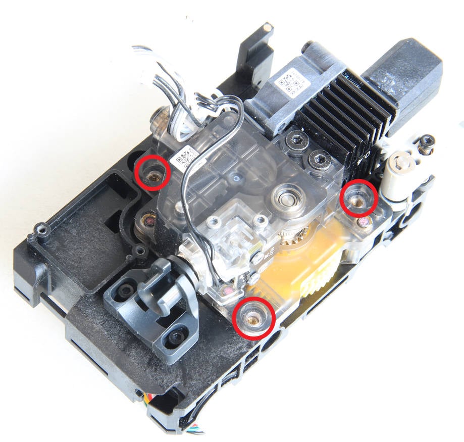
Remove the 3 screws with an H2.0 hex key, and remove the extruder and the hot end.

Step 7 - Remove the extruder motor
Remove 2 screws with an H2.0 hex key and remove the extruder motor.

Step 8 - Install the extruder motor
Install the new extruder motor onto the toolhead front carriage of the slider, ensuring that the motor cable is positioned on top. Then, secure the motor in place by tightening 2 screws.
 Step 9 - Install the extruder
Install the extruder and the hot end together on the toolhead front carriage of the slider, and then secure it with 3 screws.
Step 10 - Install the toolhead front carriage assembly of the toolhead
Before installation, ensure that the springs are correctly positioned and that both copper sleeves are inserted into the corresponding grooves on the back cover of the slider. Then, carefully install the toolhead front carriage assembly of the slider, being cautious not to press against the motor cable.
 Step 11- Lock screws (4+4)
Lock the screws to secure the toolhead front carriage assembly of the slider. Please tighten the screws in the order of 1~8 as shown in the figure below.
 Step 12 - Install the bambu micro lidar
Install the bambu micro lidar under the toolhead and secure it with 2 screws.

Step 13 - Install the LOGO LED cable
Install the LOGO LED cable.

Step 14 - Install the TH board assembly, assemble the toolhead
To verify completion/success
Power ON the printer.
Click on the extruder button on the screen to verify that the motor can drive the extruder as expected.
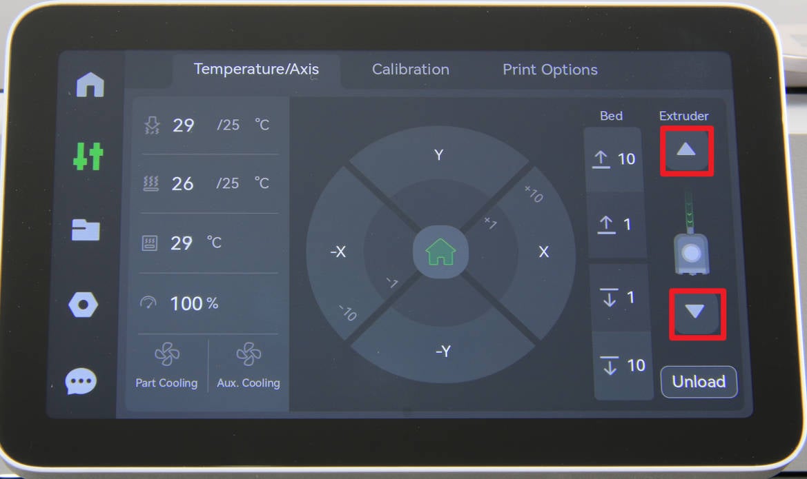
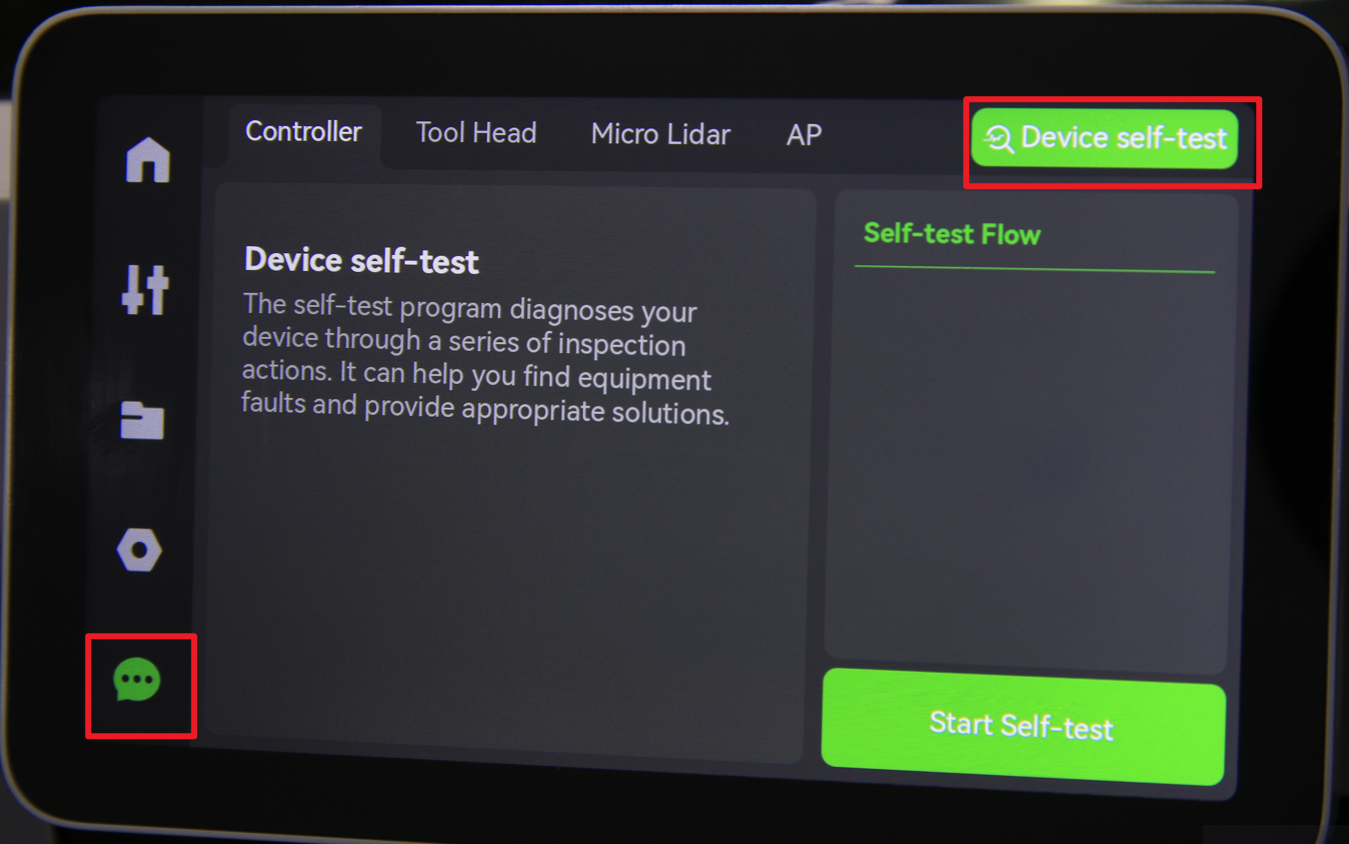
Run a self-test and ensure that there are no error messages associated with the toolhead.