


Toolhead Board - A2L for Bambu
Couldn't load pickup availability
Use this text to encourage communication or promote sharing on social networks.
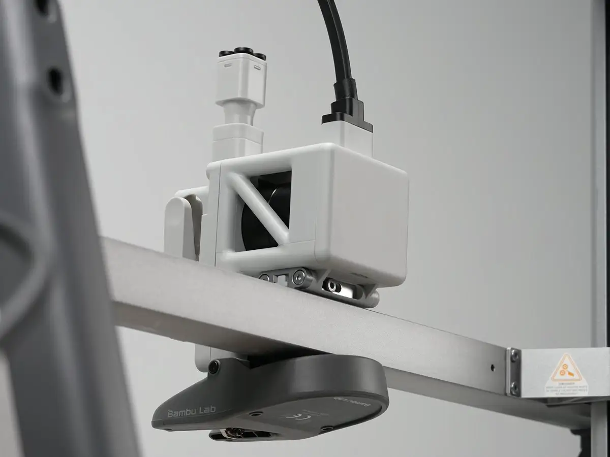
The Toolhead Board is the main circuit board of the toolhead which provides connectivity to the toolhead parts, including the hotend heating assembly, extruder unit, hotend cooling fan, filament sensor, etc.
In the Box
- Toolhead Board *1
- Mylar Sheet *1
- BT2x8 Screw *3
Compatibility
A2L
TH Board Replacement Guide for the A2L
In this wiki, you will learn how to replace the TH Board on the A2L.
A2L Toolhead (TH) Board

Important Reminder
The cooling fan for hotend, part cooling fan, and eddy current coils plug on the TH board use this small connector design. When unplugging, hold the plug base with your hand and lift vertically away from the PCB to unlock the plug./ Do not apply force horizontally to avoid damaging the plug.

Required Tools and Materials
TH board (Replace the corresponding parts according to the actual fault condition)
H1.5 allen key
Tweezers (optional)
Safety Warning
⚠️ IMPORTANT!
It's crucial to power off the printer before conducting any maintenance work, including work on the printer's electronics and tool head wires. Performing tasks with the printer on can result in a short circuit, leading to electronic damage and safety hazards.
During maintenance or troubleshooting, you may need to disassemble parts, including the hotend. This exposes wires and electrical components that could short circuit if they contact each other, other metal, or electronic components while the printer is still on. This can result in damage to the printer's electronics and additional issues.
Therefore, it's crucial to turn off the printer and disconnect it from the power source before conducting any maintenance. This prevents short circuits or damage to the printer's electronics, ensuring safe and effective maintenance.
Remove the TH Board
Step 1. Remove the Toolhead Rear Cover
Use your hand or the end of tweezers to hook into the groove at the bottom of the toolhead rear cover and lift upward to remove the rear cover.
Step 2. Remove Toolhead Cables
Use an H1.5 allen key to remove the four screws shown and lift upward to unplug the toolhead cables.

Step 3. Remove Some TH Board Connectors


Connectors 1, 2, and 3 are of the same type. When unplugging, **hold the plug base with your hand and lift vertically away from the PCB to unlock the plug.**Do not apply force horizontally to avoid damaging the plug.
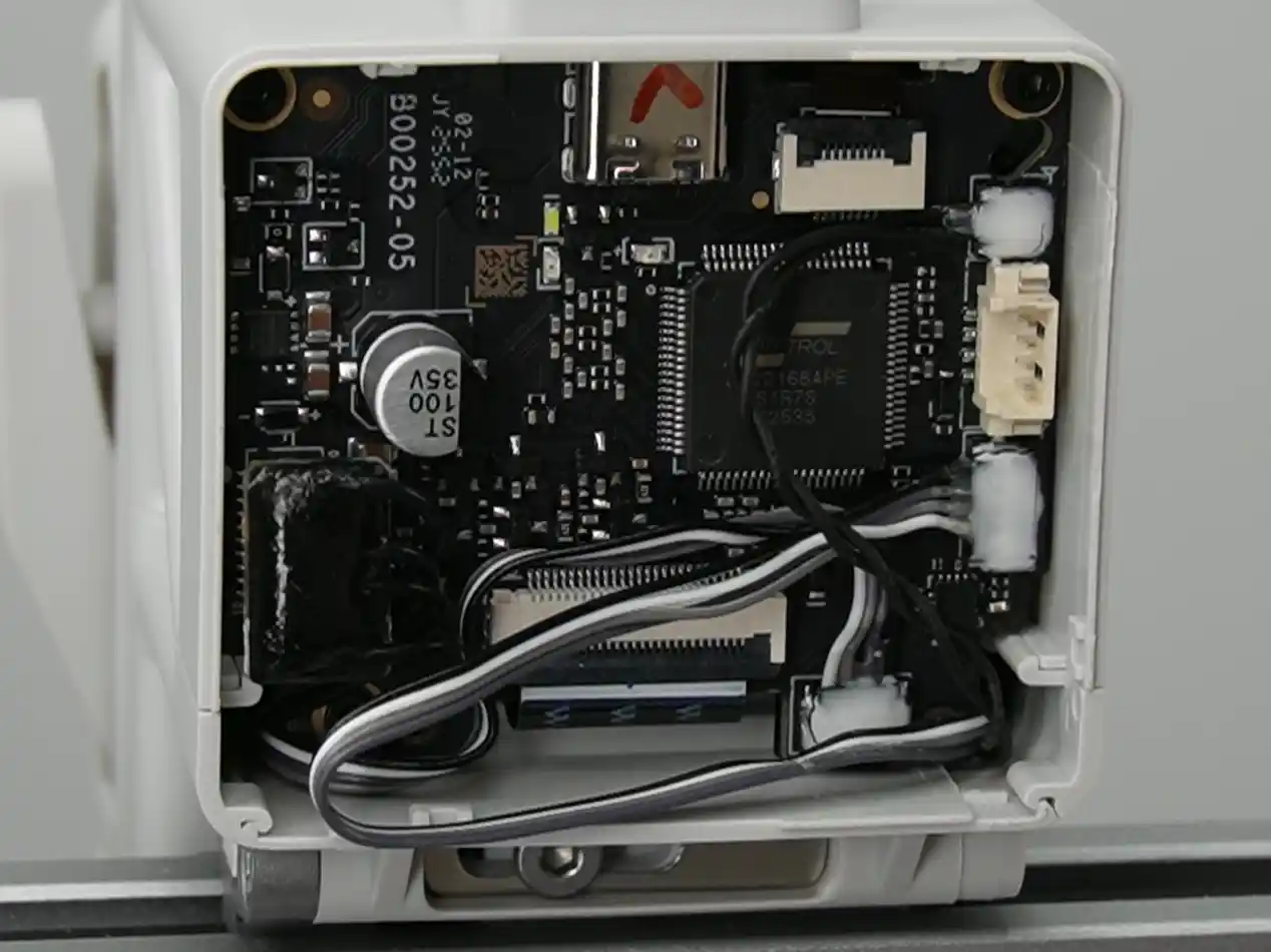
Connector 4 can be pulled straight upward to unplug.

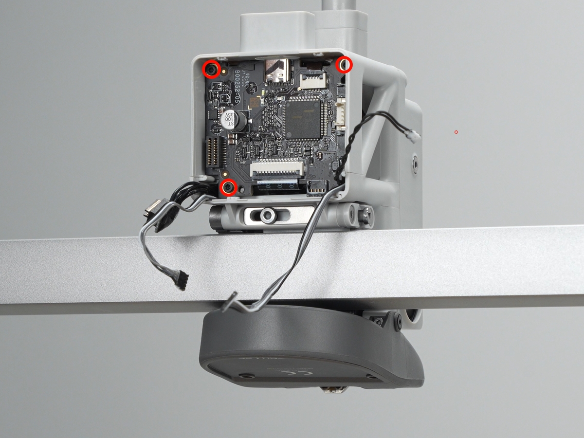
Step 4. Remove TH Board
Use an H1.5 allen key to unscrew the three screws.

Pull the TH board outward slightly, disconnect connectors 5 and 6. Lift the black locking tab upward to unlock, then unplug the FPC cables.
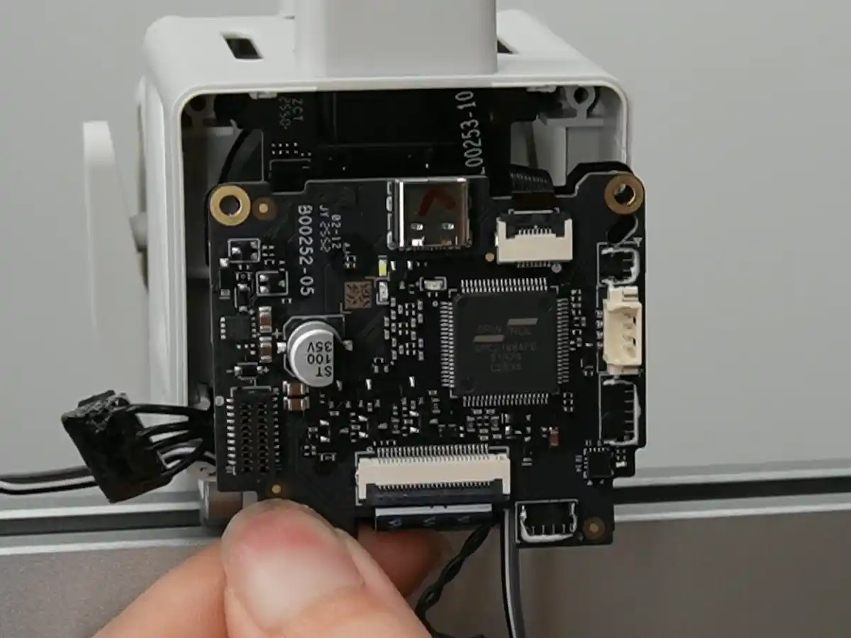
Disconnect the connectors on the back of the TH board and remove the TH board.

Install the TH Board
Step 1. Install the TH Board
1.Connect adapter board: Align the new TH board with the micarta sheet (pay attention to the orientation of the micarta sheet) and insert the plug on the back.

2.Flip the TH board and insert the Load Hall Board and extruder motor FPC cables.

ℹ️ Note: The metal contacts of the FPC cable should face the TH board. After fully inserting the cable, secure the locking tab.
3.Organize cables on both sides, push the TH board into the toolhead bracket, and secure with three screws.
ℹ️ Note: Before tightening screws, be sure to check that no cables are pinched beneath the TH board!Avoid damaging cables when securing screws.
Step 2. Connect TH Board Plugs
Reconnect the remaining cables to the TH board in order. Depending on the connector type, you may use different methods to connect the plugs.
Connectors 1, 2, and 3 are of the same type. Align the plug with the socket and press until they are fully seated.
Connector 4 can be plugged in directly.
Step 3. Install the Toolhead Cables
Insert the toolhead cables into the toolhead and use an H1.5 allen key to secure four screws.

Step 4. Install the Toolhead Rear Cover
First align the locking tabs on the top of the toolhead rear cover, then close the cover. Press the lower left and right edges of the cover and check if the edges are locked properly.
Verifying Success
✅ Connect power and turn on. Start a print test: if the printing process proceeds smoothly with no error messages, the replacement is successful.