


Upgrade Toolhead Hotend PCB Board for Snapmaker-U1
Couldn't load pickup availability
Use this text to encourage communication or promote sharing on social networks.
FIT FOR SNAPMAKER U1: Direct replacement printhead circuit board for Snapmaker U1. Matches original mounting holes and features upgraded buckle terminals. Compatible with stock and ceramic hotend versions. Not fit for J1/J1S.
PLUG & PLAY EASY INSTALLATION: No soldering or firmware modification required. Simply unplug the old board and plug in this replacement. Get your printer running in minutes.
EXPANSION FOR DIY UPGRADES: Expansion interfaces allow you to add RGB lighting, PT100/PT1000 sensors, or filament runout detection. Customize your toolhead control board for DIY projects.
HIGH-PERFORMANCE MCU FOR STABLE PRINTING: High-performance MCU ensures stable signal transmission and quick response. Reduces print interruptions and improves printing accuracy.
REPLACEMENT: Factory match for Snapmaker U1. Restore your printer with a direct replacement circuit board.
U1 toolhead PCB replacement guide
Location
The PCB is located inside the toolhead and can only be replaced after removing the housing.
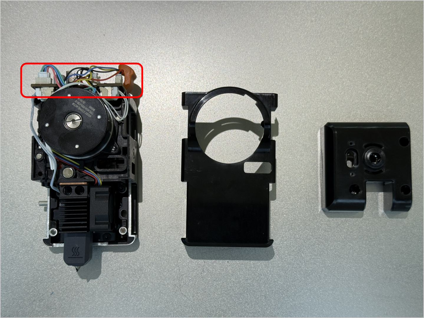
Terminology
Different from our official term, some people may use the following terms to describe this component:
Tool head PCB
Toolhead board
Print head PCB
Difficulty and Time Estimate
Difficulty:★☆☆☆☆ (Easy)
Estimated Time:15 minutes
When to Replace
When the toolhead PCB is damaged or malfunctioning.
When pogo pins need to be replaced. (The toolhead PCB integrates pogo pins, and each set of pogo pins is rated for 250,000 swaps)
Tools and Parts Required
H1.5 hex key
H2.0 hex key
New U1 toolhead PCB
Part 1. Remove the Toolhead
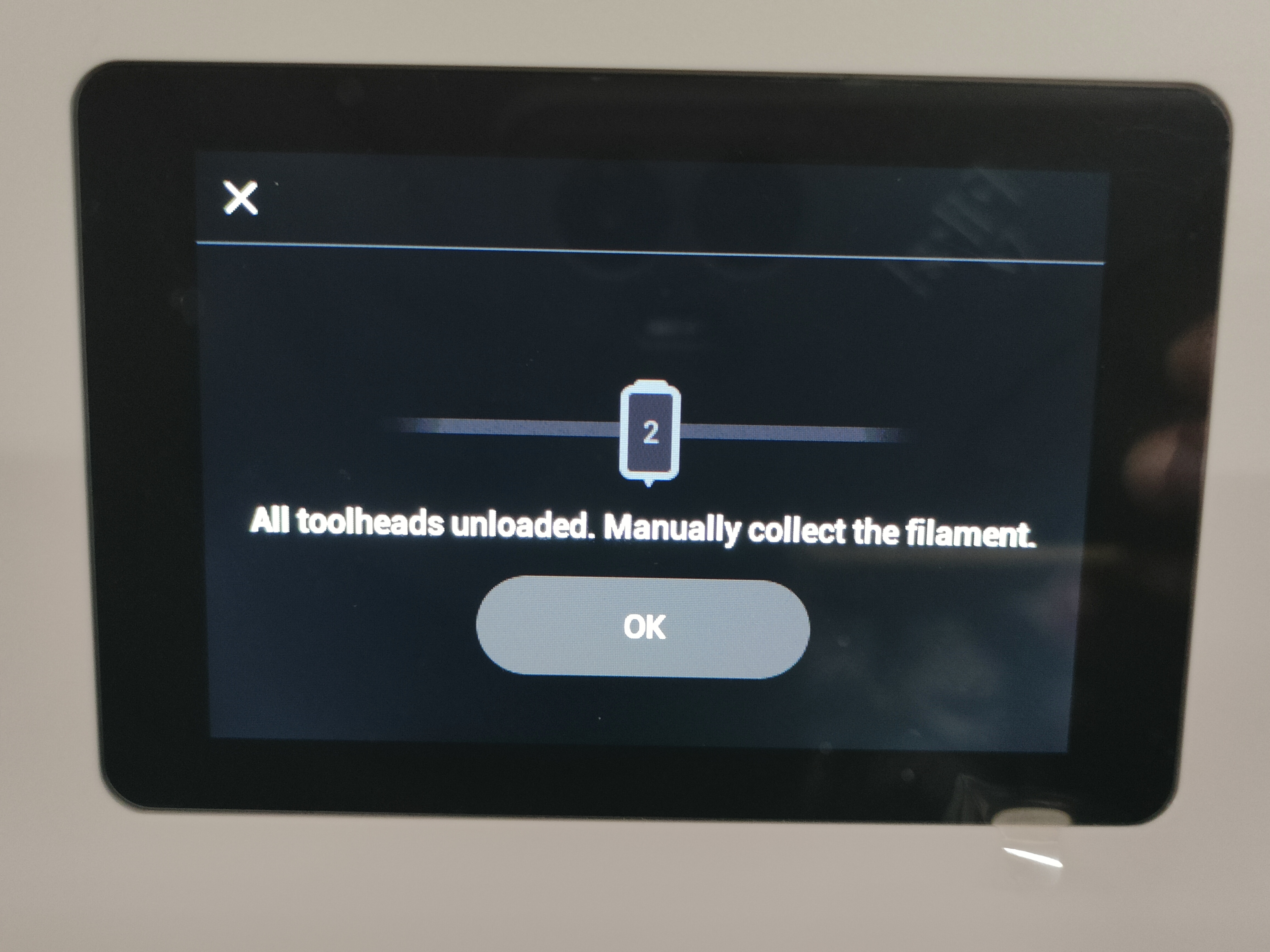
Step 1. Unload filament
Tap the specified area on the touchscreen (Highlighted in red in the image below).
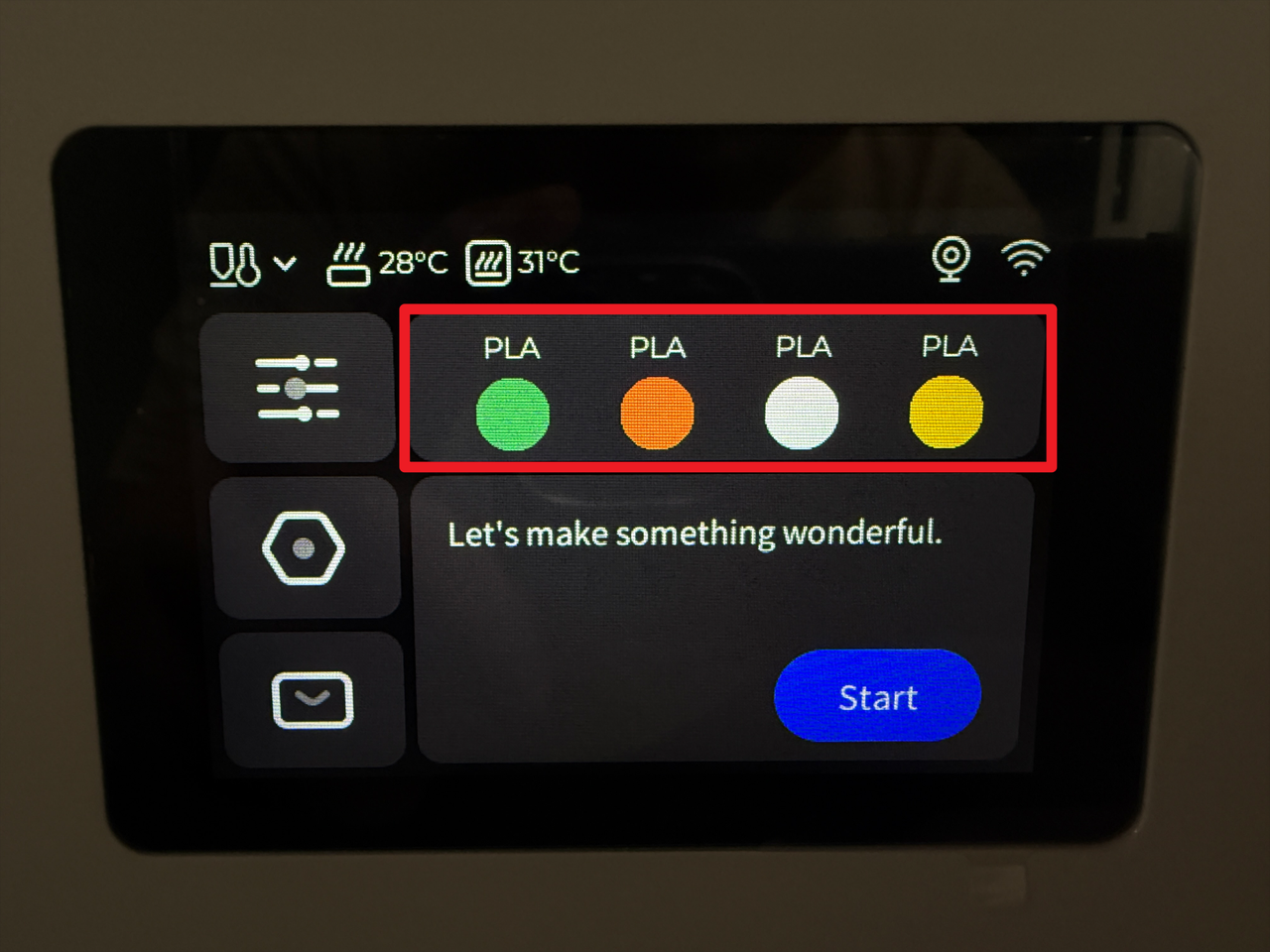
Tap "Unload Mode".
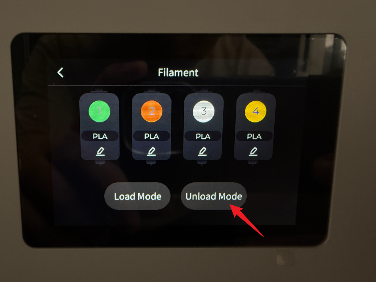
Select the target toolhead (e.g., No.2) and tap "Unload".
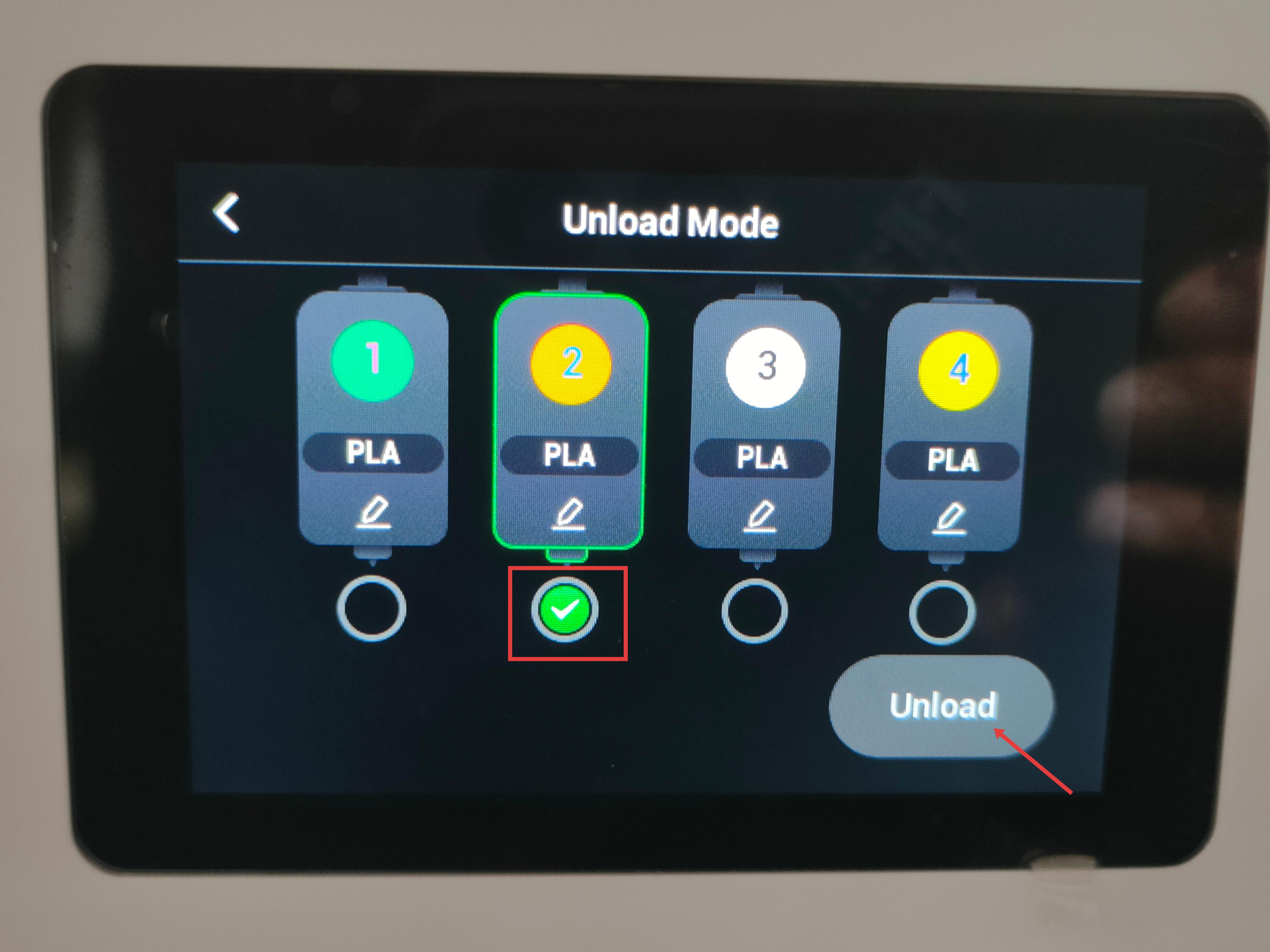
Wait for the system to automatically complete the filament unloading.
Step 2. Detach the toolhead from the docking bracket

For head No.1: Slide to the right until the locating pin is fully visible.

For heads No.2/3/4: Slide the toolhead to the left until the locating pin is fully visible.

Step 3. Remove filament and guide tube
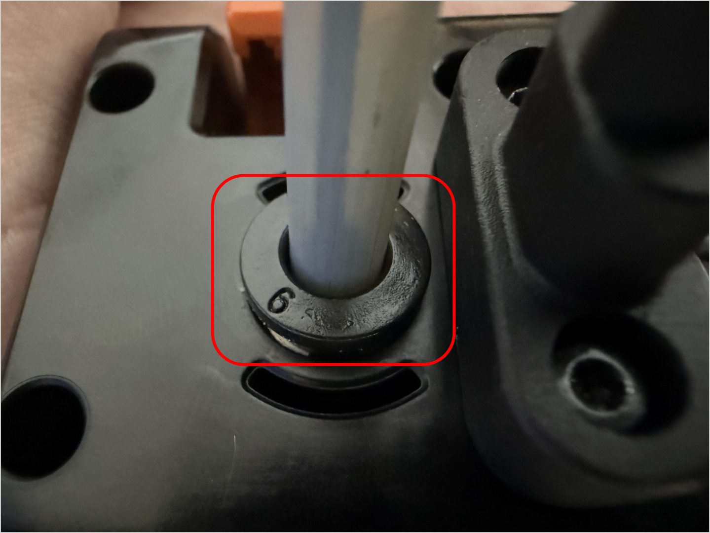
Press the quick-release fitting and remove the filament and guide tube.
Step 4. Disconnect USB and remove the toolhead
Use the H2.0 hex key to remove the two mounting screws.
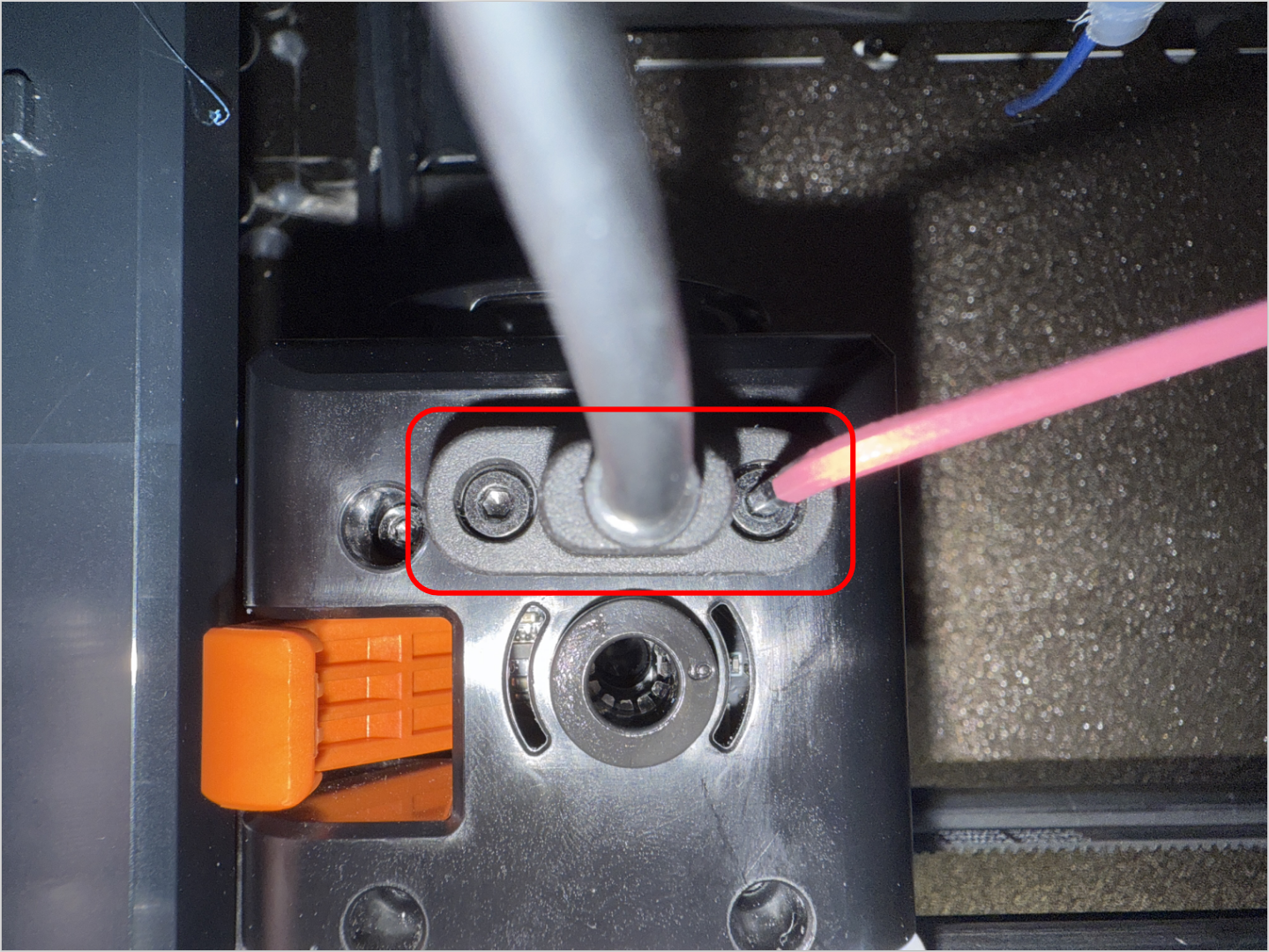
Unplug the USB cable and then carefully remove the toolhead.
Part 2. Remove the Old PCB
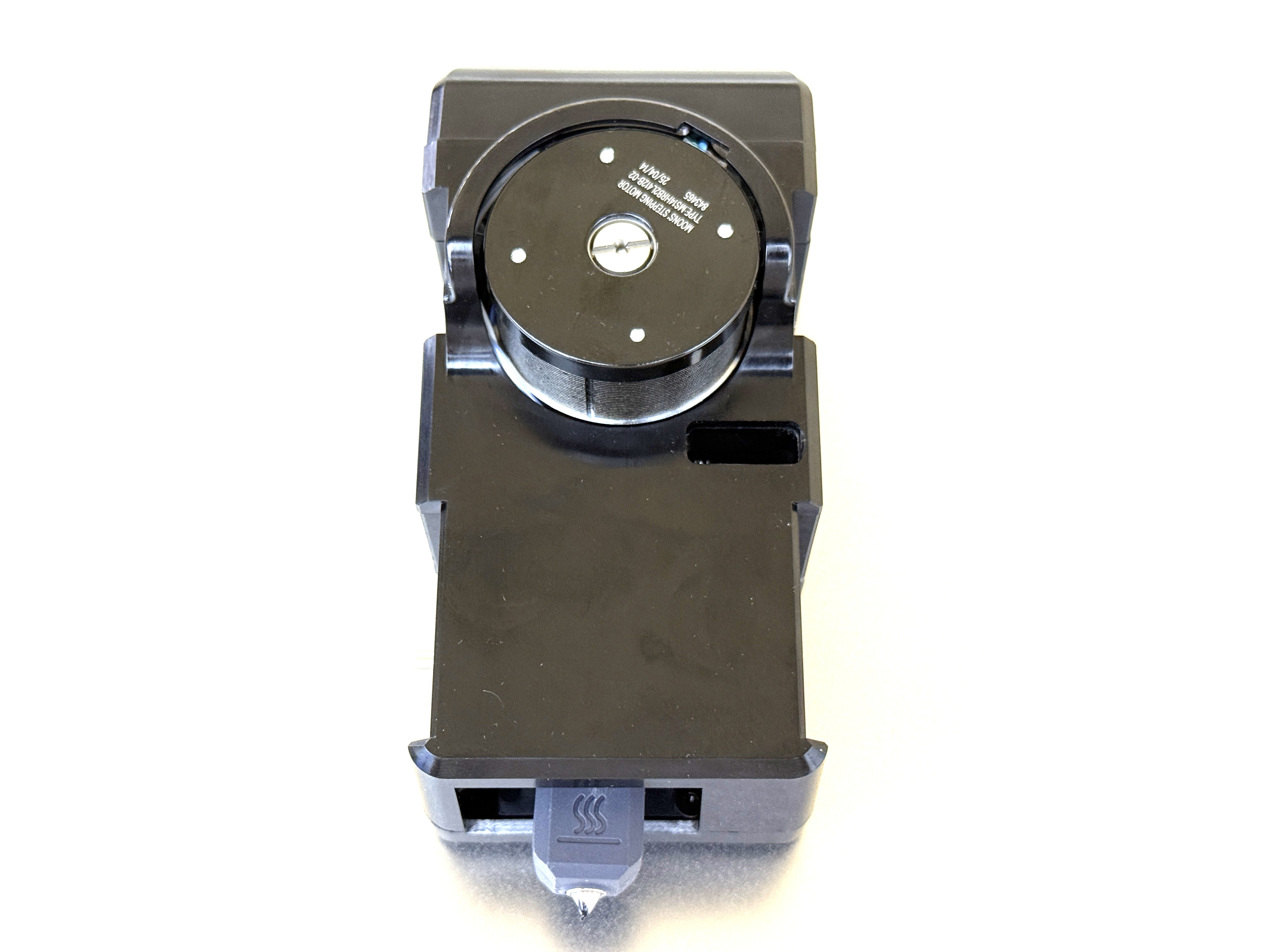
Step 5. Remove top cover and back cover
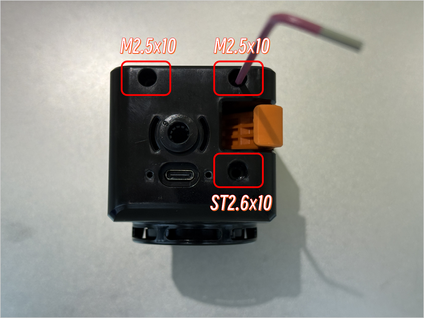
Use the H2.0 hex key to remove the three screws securing the top cover of the toolhead.
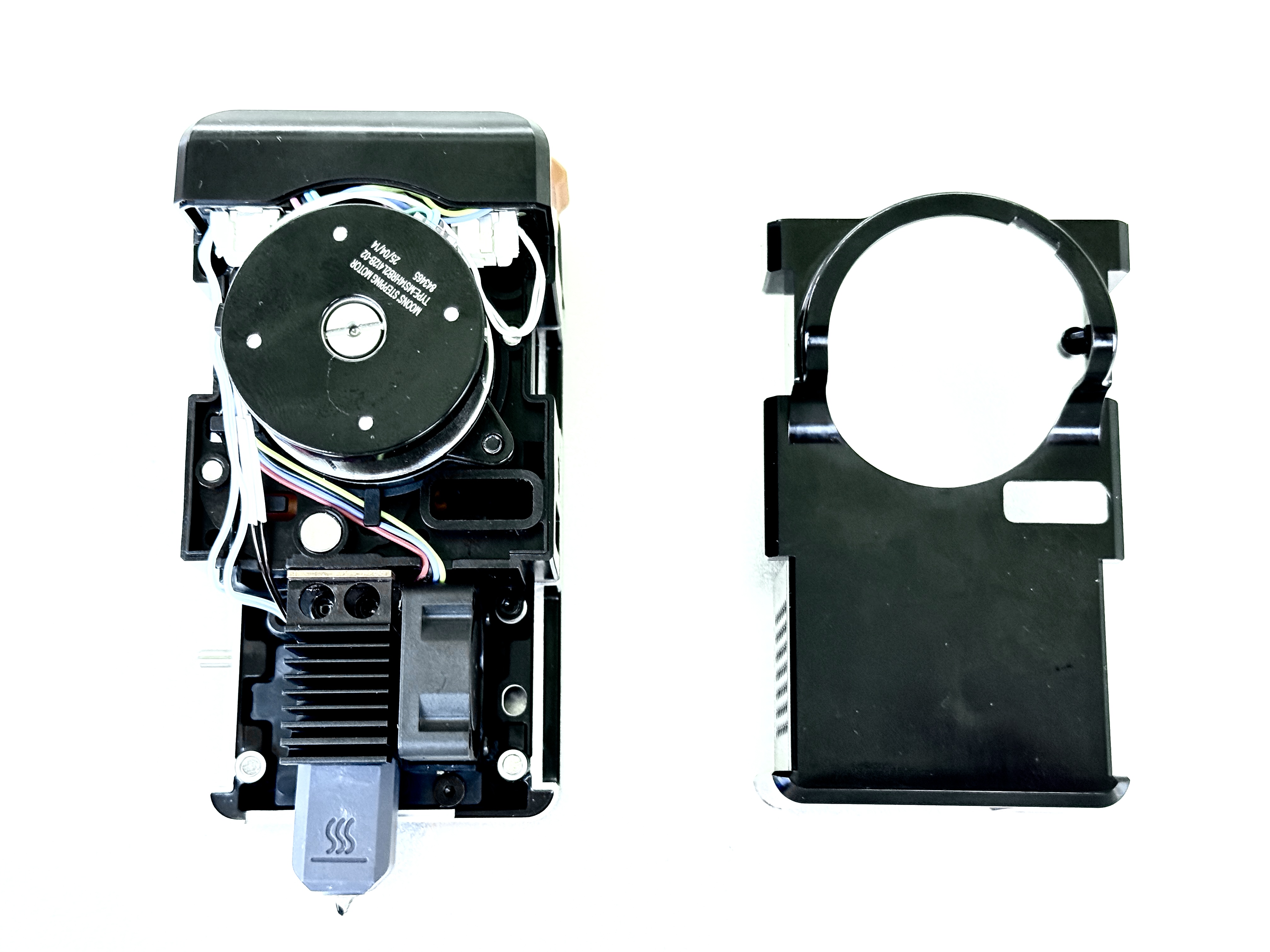
Remove the back cover of the toolhead.
Step 6. Disconnect the cables and remove the PCB
Disconnect the cables from the PCB.
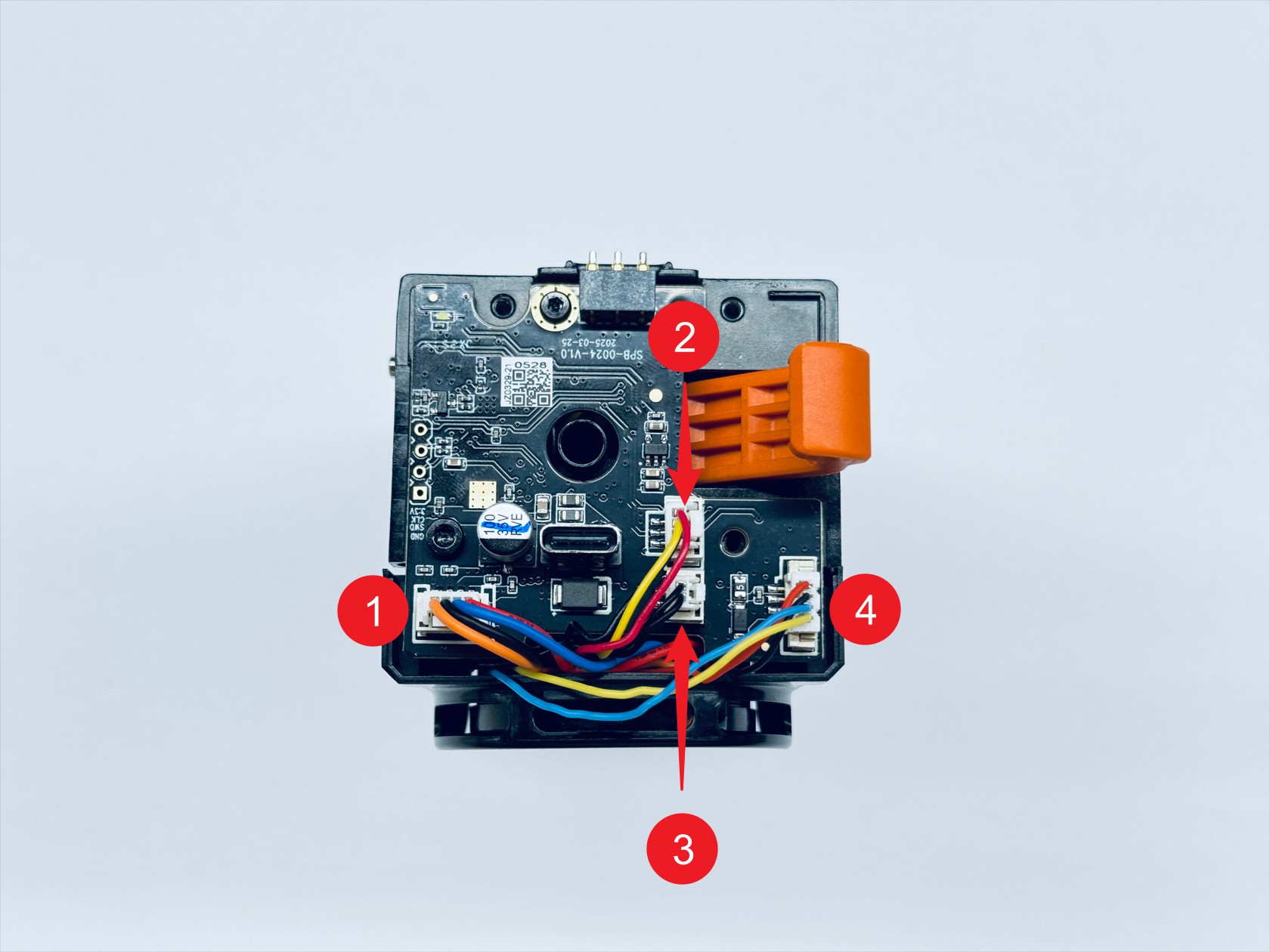
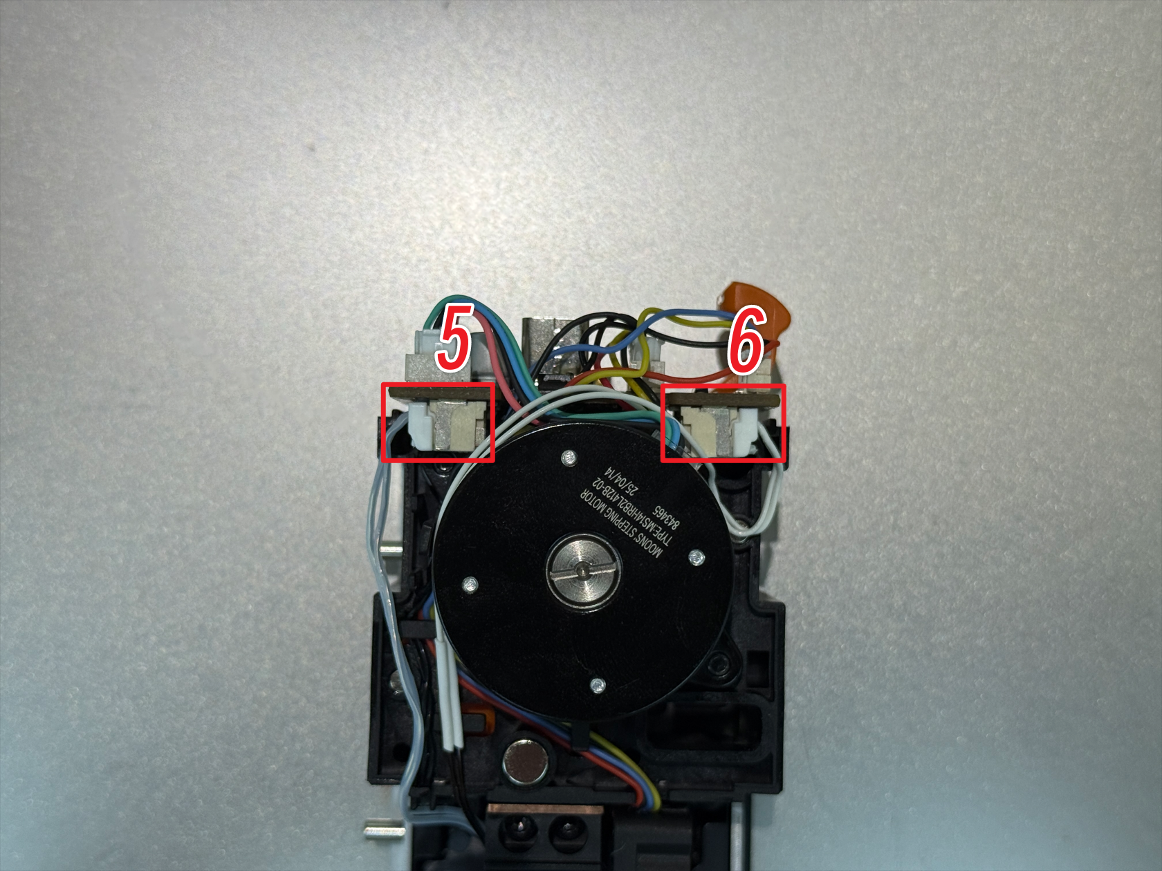
When installing the new toolhead PCB, please refer to the wiring diagram below.

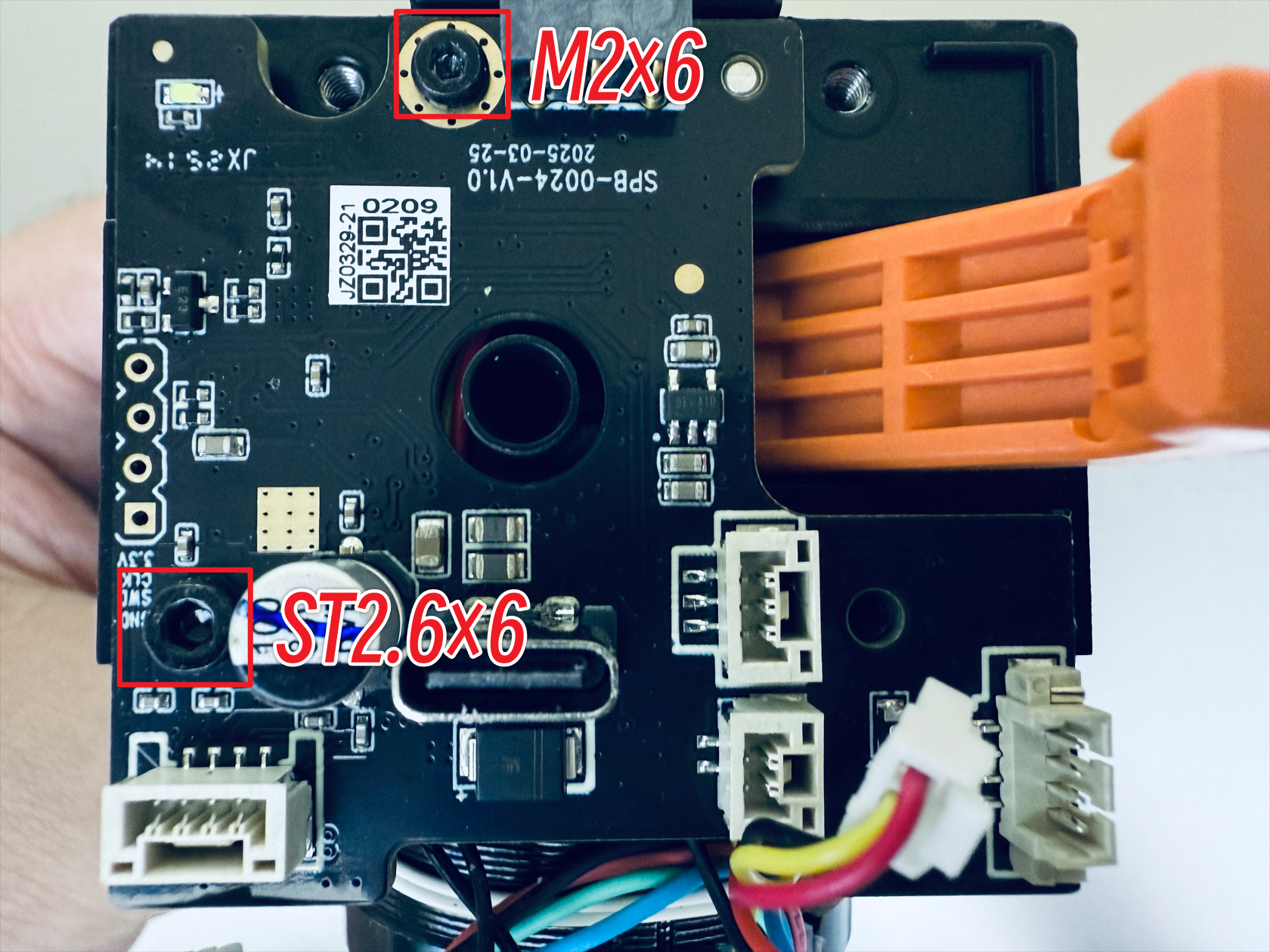
Use the H1.5 hex key to remove the M2×6 screw, and the H2.0 hex key to remove the ST2.6×6 screw, then take out the old PCB.

Part 3. Replace the PCB
Step 7. Install the new PCB
Place the new PCB in the position shown in the image. Use the H1.5 hex key to tighten the M2×6 screw, and the H2.0 hex key to tighten the ST2.6×6 screws.
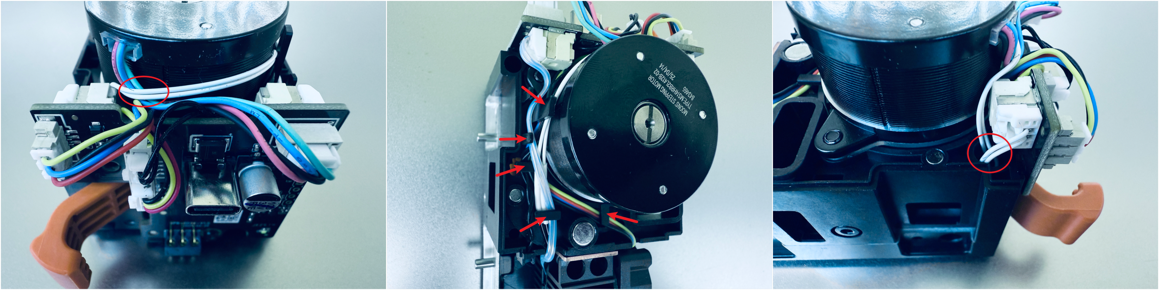
Reconnect all PCB cables as labeled in the image.
Organize cables.
Step 8. Install the toolhead housing
Install the top cover of the toolhead.
Install the back cover of the toolhead.
Part 4. Install the toolhead
Step 9. Place the toolhead onto the docking bracket
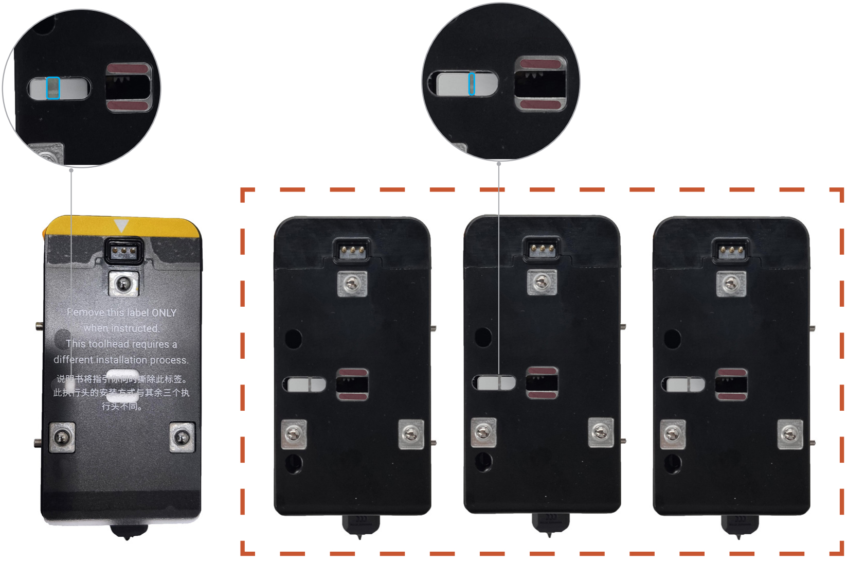
Before installing the toolhead, please make sure the sliders are in the correct positions. The slider for Toolhead No. 1 should be set to the far left, while the sliders for Toolheads No. 2, 3, and 4 should all be set to the far right.
You can use a hex key to adjust the slider and make sure the red mark on the slider is visible.
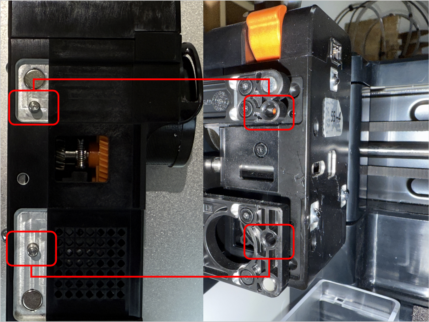
Align the hole on the toolhead with the long locating pin on the docking bracket, and push inward until it stops.
The illustrated side of the toolhead should face inward.
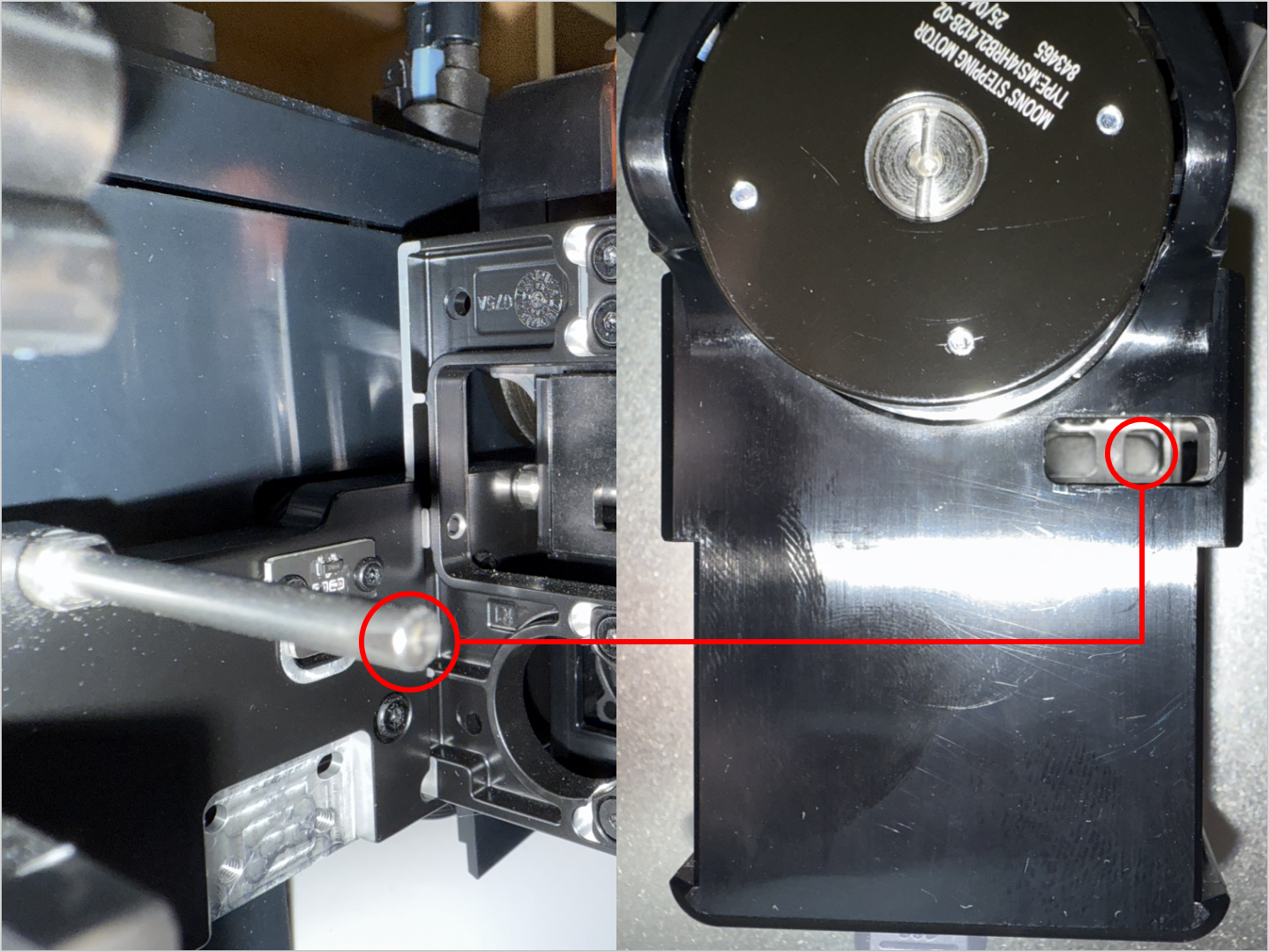
Align the two locating pins on the toolhead with the holes shown on the mount.
For No.1 head: hole is to the left of the pins
For No.2/3/4 heads: hole is to the right of the pins
Step 10. Connect and secure the USB cable
Plug in the USB cable and fasten the two screws with the H2.0 hex key.
Step 11. Load filament
While pressing part 1, as highlighted in the image below, insert the filament into part 2 until it reaches the end.
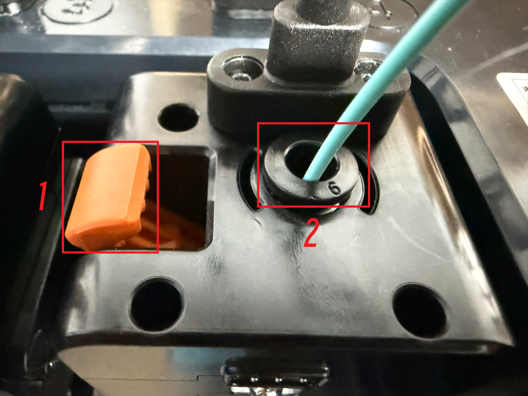
Finally, connect the guide tube. The toolhead installation is now complete.
Verification
Check whether the indicator light on the toolhead PCB turns on after powering on.
Check whether the toolhead is recognized properly.
Check whether the toolhead's heating and printing functions are working correctly.