


Nozzle Eddy Sensor for Bambu Lab H2C/H2D
Couldn't load pickup availability
Use this text to encourage communication or promote sharing on social networks.
The Nozzle Eddy Sensor is used to detect whether the nozzle is wrapped by molten filament.
Installation
Learn more about the Nozzle Eddy Sensor - Right for H2D on Bambu Lab Wiki.
Learn more about the Nozzle Eddy Sensor - Right for H2C on Bambu Lab Wiki.
Learn more about the Nozzle Eddy Sensor - Left on Bambu Lab Wiki.
In the Box For Nozzle Eddy Sensor - Right
For H2D
- Nozzle Eddy Sensor - Right*1
- BT2-5 Screw*2
- M2-5 Screw*2
In the Box
For Nozzle Eddy Sensor - Left
- Nozzle Eddy Sensor - Left*1
- BT2-6 Screw*1
Compatibility
H2D and H2D Laser
H2C and H2C Laser
Replace H2D Nozzle Eddy Sensor
Important Reminder
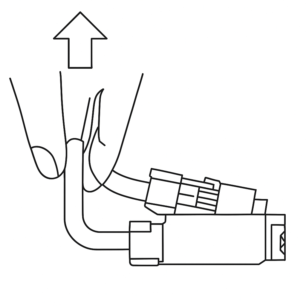
The eddy sensor coil connectors on the H2D feature this compact connector design. When removing the connector, please hold the base of the connector with your hand and lift straight up, perpendicular to the PCB surface, to unlock it. Never apply force in the horizontal direction to avoid damaging the connector.
Left/Right Nozzle Eddy Sensor
Left nozzle eddy sensor is mounted on the rear of the nozzle lifting rail and right nozzle eddy coil is mounted on the top of the right hotend.
Spare parts for the left nozzle eddy sensor include:
1.Left nozzle eddy sensor × 1
2.BT2x6 screw (for securing left nozzle eddy sensor) × 1
Spare parts for the right nozzle eddy sensor include:
1.Right nozzle eddy sensor × 1
2.BT2×5 screw (for securing toolhead sensor FPC cable) × 2
3.M2×5 screw (for securing right nozzle eddy sensor) × 2
When to use
Nozzle eddy sensor is damaged;
Bambu Lab technical support confirms replacement is required.
Tools and materials needed
1.New Left/Right nozzle eddy sensor (replace corresponding sensor as needed)
2.H2.0 Allen key
3.H1.5 Allen key
Specifications and quantities of screws involved in replacing the H2D left nozzle eddy sensor (it is recommended to keep the removed screws properly to avoid loss):
BT3x8x4pcs;
BT3x20x2pcs;
BT2.6x8x2pcs;
M1.6x4x2pcs;
M2x5x1pcs;
M2.5x2x2pcs;
BT2x6x2pcs;
Specifications and quantities of screws involved in replacing the H2D right nozzle eddy sensor (it is recommended to keep the removed screws properly to avoid loss):
BT3x8x4pcs;
BT3x20x2pcs;
BT2.6x8x2pcs;
M1.6x4x2pcs;
MG2.5x19x5x1pcs;
M2.5x7x3pcs;
BT2x6x1pcs;
Safety Warning
IMPORTANT!
It's crucial to power off the printer before conducting any maintenance work, including work on the printer's electronics and tool head wires. Performing tasks with the printer on can result in a short circuit, leading to electronic damage and safety hazards.
During maintenance or troubleshooting, you may need to disassemble parts, including the hotend. This exposes wires and electrical components that could short circuit if they contact each other, other metal, or electronic components while the printer is still on. This can result in damage to the printer's electronics and additional issues.
Therefore, it's crucial to turn off the printer and disconnect it from the power source before conducting any maintenance. This prevents short circuits or damage to the printer's electronics, ensuring safe and effective maintenance. For any concerns or questions about following this guide, we recommend submitting a technical ticket regarding your issue and we will do our best to respond promptly and provide the assistance you need.
Remove the Left Nozzle Eddy Sensor
Step 1: Remove the Left Hotend and Left Hotend Cooling Fan Air Duct
First, check whether the flow blocker is positioned at the bottom of the right hotend. If it is located at the bottom of the left hotend, its interference during removal may cause the blocker spring to bend. Manually actuate the swing lever to move the flow blocker to the right side. Ensure that the tail of the flow blocker securely attaches to the magnet on the right side of the nozzle blocker magnet bracket to confirm proper positioning.
Remove the silicone sock for hotend, release the latch, and detach the left hotend. Use an H2.0 Allen key to remove one M2×5 screw securing the left hotend cooling fan air duct, then extract the air duct.

Step 2: Remove the Extruder Connection Board
To facilitate disconnecting the left nozzle eddy sensor's wiring, refer to this Wiki guide for removing the extruder connection board:
Replace H2D Extruder Connection Board/TH Board/FPC Cable
Step 3: Remove the Flow Blocker Magnet Bracket
To improve accessibility, you may first remove the flow blocker magnet bracket. Use an H2.0 Allen key to unscrew two M2.5×2 screws securing the bracket, then lift it away.
Step 4: Remove the left nozzle sensor
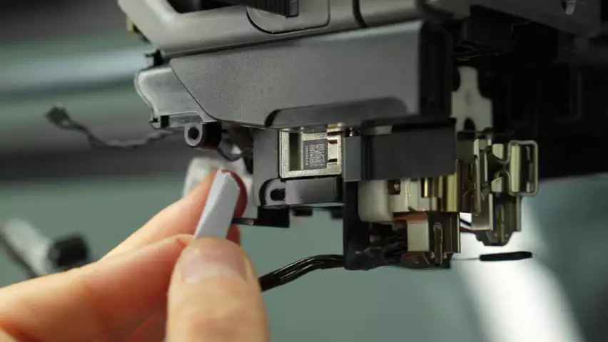
Remove the tape covering the left nozzle eddy current sensor interface. The plug needs to be diagonally lifted away from the plane, not pulled along the plane.
The left nozzle eddy sensor cable is stuck in the cable slot of the cooling fan for hotend. You need to remove the cable from the cable slot on the right first, and then pull the cable out of the toolhead. There are two cable slots on the right, one large and one small. The large cable slot at the arrow below is used to store the left hotend heating assembly cable, and the small cable slot at the arrow above is used to organize the left nozzle eddy sensor plug, right nozzle eddy sensor plug and lifting Hall plug cables.
You can first remove the left hotend heating assembly connector from the large cable slot, and then remove the left nozzle eddy sensor connector from the small cable slot.
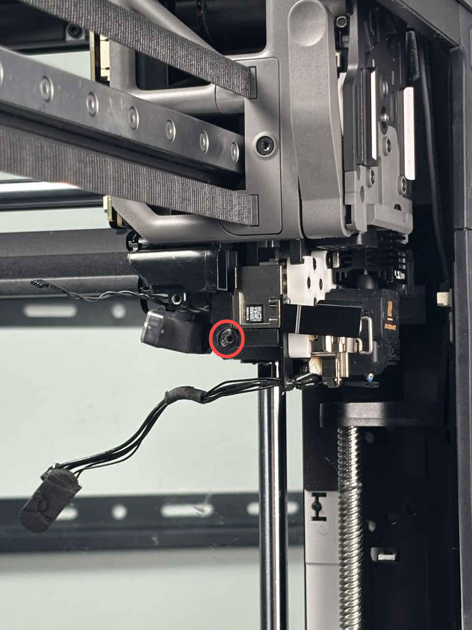
 Use an H2.0 hex wrench to remove a fixed screw (BT2x6). Please note that to ensure transportation reliability and installation consistency, the factory applies some glue when assembling the left eddy current coil. Therefore, after you remove the screw, you may need to apply a little force to take out the left eddy current coil from the side. When installing the new eddy current coil, there is no need to apply glue.
Installation of Left Nozzle Eddy Sensor
¶Step 1: Install the Left Nozzle Eddy Sensor
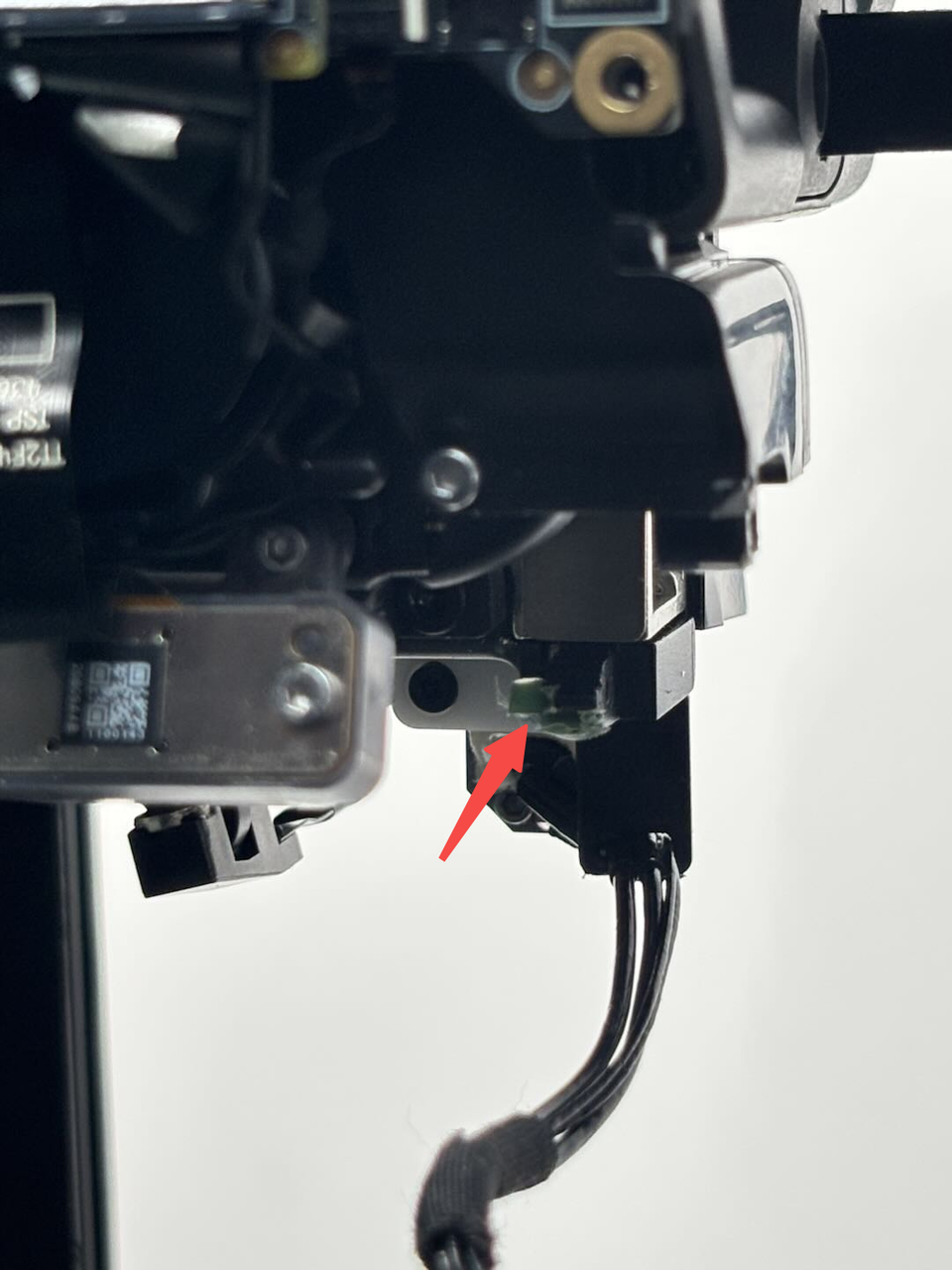
Since residual adhesive on the toolhead may affect the installation accuracy of the left nozzle eddy sensor, you can first use a scraper to remove any remaining adhesive (the adhesive appears green in color).
Insert the new left nozzle eddy sensor into the toolhead, then use an H2.0 Allen key to fasten the screw without fully tightening it. Prepare an A4 sheet of paper and fold it in half.
The gap between the left nozzle eddy sensor and the lifting slider should be approximately 0.2mm, which is roughly the thickness of a folded A4 sheet.

Next, insert the folded A4 paper between the left nozzle eddy sensor and the lifting slider. Hold the sensor in place with your hand and gently pull the paper to check if it slides smoothly (there should be slight resistance but it should still be easy to remove). If the movement is just right, use the H2.0 Allen key to tighten the screw completely.
While tightening the screw, keep your hand steady on the sensor to avoid any misalignment. Once the screw is secured, remove the A4 paper.
 Route the left nozzle Eddy sensor’s cable through the small cable slot first. Align the connector with the metal side facing upward and plug it flat into the port on the TH board. Then secure it with tape.

The wiring for the left hotend heating assembly will be organized and installed in Step 3 – Install the Extruder Connection Board.

Step 2. Install the Nozzle Block Magnet Bracket
Align the nozzle block magnet bracket with the screw holes, then use an H2.0 Allen key to tighten the two securing screws:

Step 3. Install the Extruder Connection Board
Refer to this Wiki guide for reinstalling the extruder connection board:
Replace H2D Extruder Connection Board/TH Board/FPC Cable
Step 4. Install the Left Hotend Fan Air Duct and Left Hotend
Reattach the left hotend fan air duct and secure it with an H1.5 Allen key by tightening one fixing screw. Then, reinstall the left hotend, lock the clips in place, and reposition the silicone sock for hotend.
Remove the Right Nozzle Eddy Sensor
Step 1: Remove the Dual Extruder Filament Guide
To facilitate the removal of the right nozzle eddy sensor, first refer to this Wiki guide to remove the dual extruder filament guide:
Step 2: Remove the Extruder Connection Board
Refer to this Wiki guide to remove the extruder connection board:
Step 3: Remove the Right Nozzle Eddy Sensor
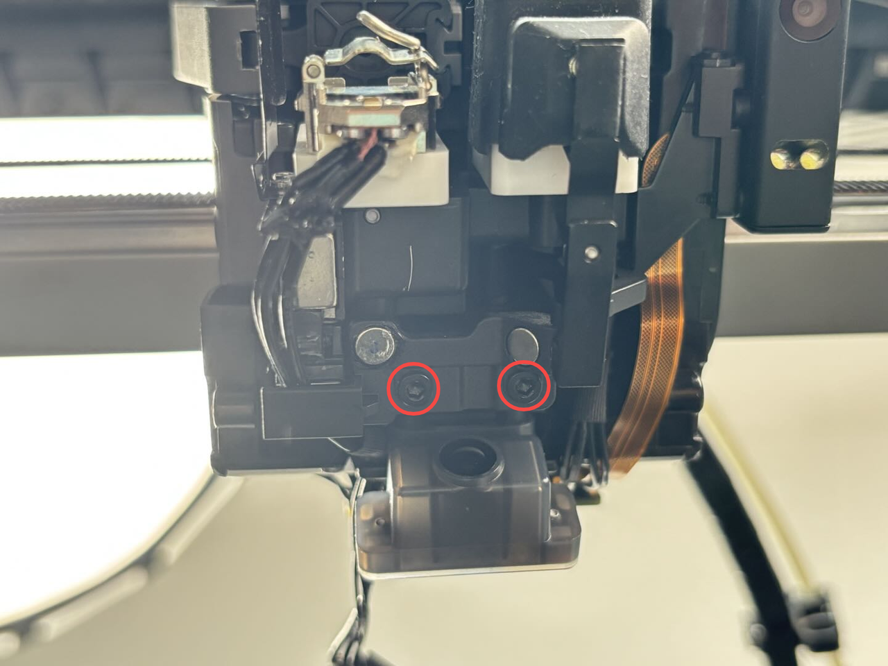
Use an H2.0 Allen key to remove the two guide screws and take out the guide. Then, use an H1.5 Allen key to remove the two screws securing the right nozzle eddy sensor.

Peel off the tape covering the right nozzle eddy sensor connector, then push the connector flat along its plane to detach it.

The right nozzle eddy sensor connector is secured in the hotend cooling fan cable clips. To remove it:
First, release the cable from both left and right clips;
Then, pull the cable out of the toolhead.
On the right side, there are two cable clips - a larger one (indicated by the lower arrow) which manages the left hotend heating assembly cables, and a smaller one (indicated by the upper arrow) that organizes the connectors for the left nozzle eddy sensor, right nozzle eddy sensor, and lift Hall sensor cables.
You can remove the left hotend heating assembly cable from the larger clip, then extract the right nozzle eddy sensor cable from its clip, and gently peel back the nozzle camera FPC cable from the lifting motor cover, allowing the right nozzle eddy sensor cable to pass underneath.
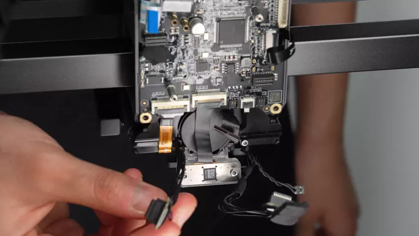
 Disconnect the right hotend heating assembly cable from the TH board, remove the right hotend heating assembly cable from the cable buckle, you can push the cable back a little, remove the cables one by one from the cable buckle, then remove the right nozzle eddy sensor cable from the cable buckle and pull out the right nozzle eddy sensor.
Install the Right Nozzle Eddy Sensor
Step 1: Install the Right Nozzle Eddy Sensor
Pass the new right nozzle eddy sensor connector through the small hole on the extruder, then align the right nozzle eddy sensor with the screw hole, and tighten the two fixing screws with an H1.5 Allen key. Then align the guide with the screw hole on the extruder, and tighten the two fixing screws with an H2.0 Allen key.

First, insert the right nozzle eddy sensor cable into the left cable buckle, then insert the right hotend heating assembly connector into the cable buckle, and then pass the right nozzle eddy sensor cable under the nozzle camera connector and insert it under the lifting motor cover;
 Insert the right nozzle eddy sensor cable into the small cable buckle inside, then insert the left hotend heating assembly connector into the large wire buckle, press the metal surface of the right nozzle eddy sensor interface upward into the interface of the TH board, and re-attach the tape.

Step 2: Install the Extruder Connection Board
Please refer to this wiki to install the extruder connection board:
Replace H2D Extruder Connection Board/TH Board/FPC Cable
Step 3: Install the Dual Extruder Filament Guide
Please refer to this wiki to install the dual extruder filament guide:
Replace H2D Dual Extruder Filament Guide
Verify the Functionality
Turn on the printer and it will be ready to print.