


Mainboard for Bambu A1 mini
Couldn't load pickup availability
Use this text to encourage communication or promote sharing on social networks.
Mainboard Replacement Guide - A1 mini
This guide shows how to replace the Main Controller Board on the A1 mini
In this guide we will show the process of replacing the Mainboard on the A1 mini
When to use?
This guide should be used if the Mainboard of the A1 mini is faulty, and needs to be replaced.
Common issues that are caused by the A1 mini Mainboard are:
Printer is not turning on
The Mainboard is damaged
Recommended by Bambu Lab Customer Support
Tools and materials needed
Bambu Lab Main Controller Board for A1 mini
H2.0 hex wrench
H1.5 hex wrench
PH2 Philips screwdriver
30 minutes of your time
Safety Warning
IMPORTANT!
It's crucial to power off the printer before performing any maintenance work on the printer and its electronics, including tool head wires, because leaving the printer on while conducting such tasks can cause a short circuit, which can lead to additional electronic damage and safety hazards.
When you perform maintenane or troubleshooting on the printer, you may be required to disassemble some parts, including the hotend. This process can expose wires and electrical components that could potentially short circuit if they come into contact with each other or with other metal or electronic components while the printer is still on. This can damage the electronics of the printer and cause further damage.
Therefore, it's essential to switch off the printer and disconnect it from the power source before doing any maintenance work. This will prevent any short circuits or damage to the printer's electronics. By doing so, you can avoid potential damage to the printer's electronic components and ensure that the maintenance work is performed safely and effectively.
Steps to remove the old Main Controller Board
1. Remove the printer's bottom housing cover
Place the printer on its side, with the Z axis pillar facing the table.
Then, remove the 16 screws holding the bottom cover in place, to access the Mainboard fan.
Please note that screws 15 and 16 are different, so keep track of them for when you will re-assemble the bottom cover.
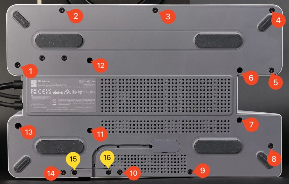
After removing the screws, gently pry out the plastic bottom cover.
You can start from the top right side, and gently work your way around the printer until the cover gets loose.
2. Remove the Mainboard fan
Start by removing the two screws holding the fan in place.
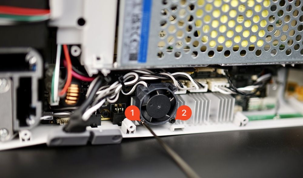
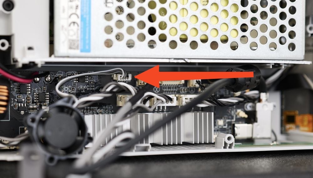
With the screws removed, gently pull the fan towards you and locate the fan cable connector.
Gently pull on the fan connector to disconnect the cable from the Mainboard.
3. Remove the USB C cable bracket and disconnect it
With the cover removed, we can proceed in removing the USB C cable bracket as shown in the image below.
This is used to hold the USB cable securely attached to the main board.
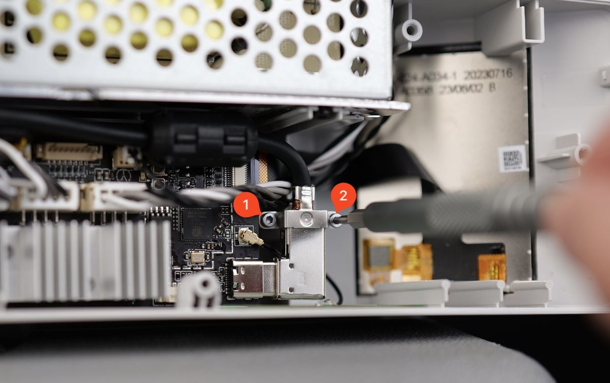
With the screws removed, you can gently disconnect it. Please make sure to pull towards the right, and not bend the cable as there is a small risk of damaging the USB connector on the board.
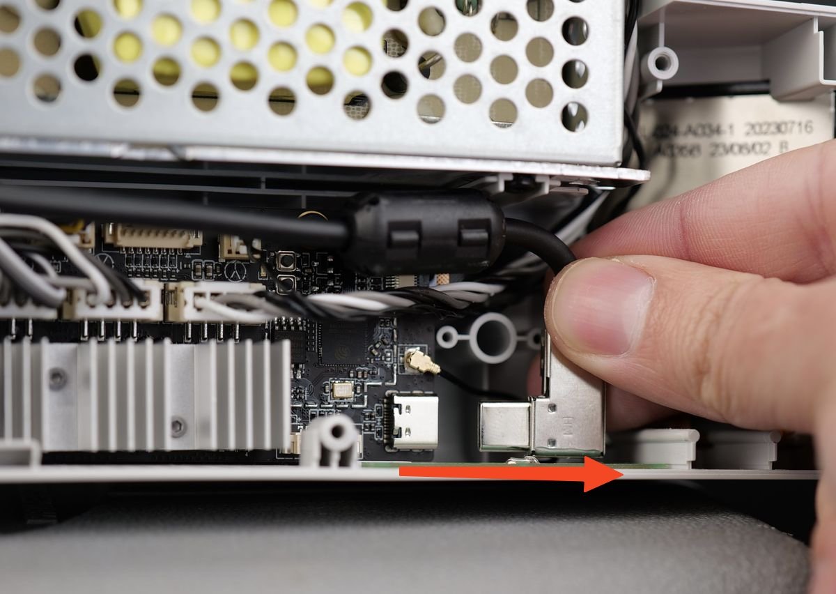
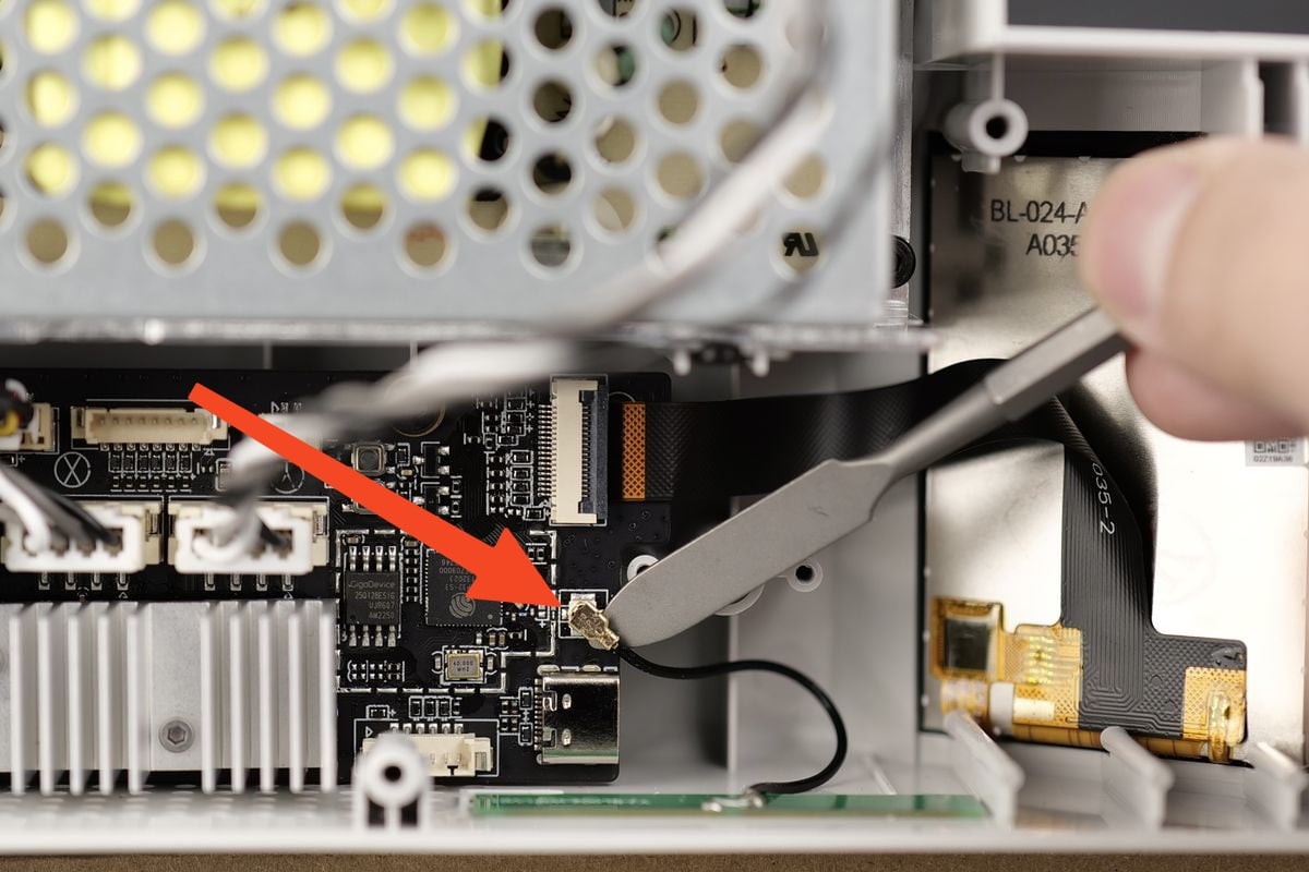
4. Disconnect the Wi-Fi Antenna connector
In the next step, gently pull the Wi-Fi Antenna cable towards you. Use a flat tool to carefully remove it.
Take extra care at this step to pull it upwards from the board to avoid damaging the Mainboard.
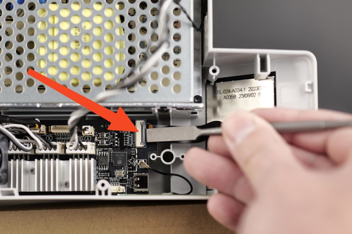
5. Disconnect the ribbon cable of the Touchscreen
In the next step, gently pull the plastic clip holding the ribbon cable towards you. It will release the ribbon cable so you can pull it out
Take extra care at this step. The clip can be easily damaged
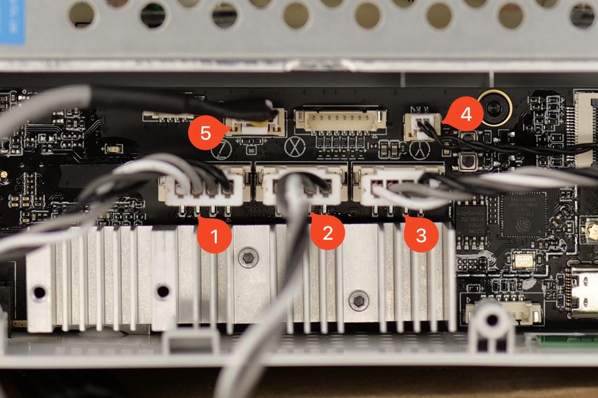
6. Remove the remaining Mainboard cables
You can now remove the remaining Mainboard cables.
Please take extra care with the cables labeled 4 and 5. They have a small clip on the bottom section that needs to be pressed when removing them.
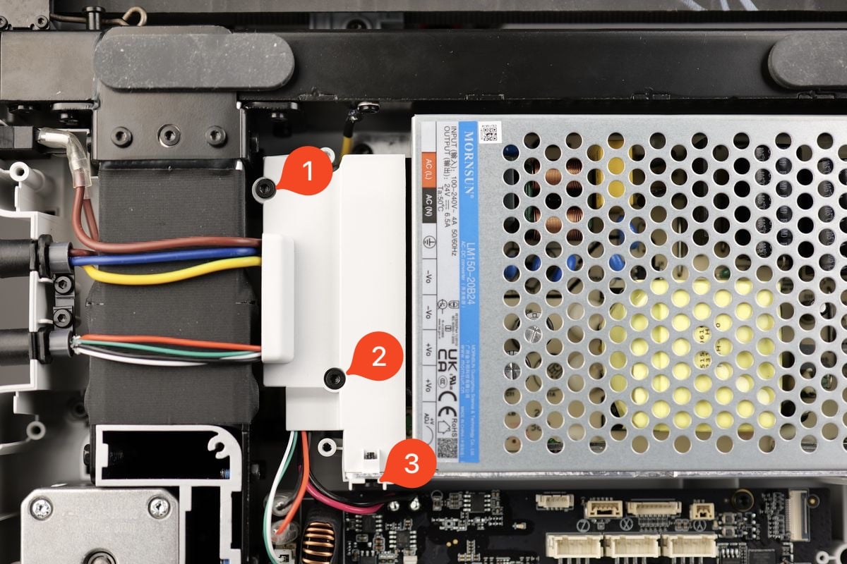
7. Remove the plastic wire cover
Carefully remove the three screws holding the plastic wire cover in place to access the power terminals of the Power Supply.
Please note that screw nr. 3 is on the side.
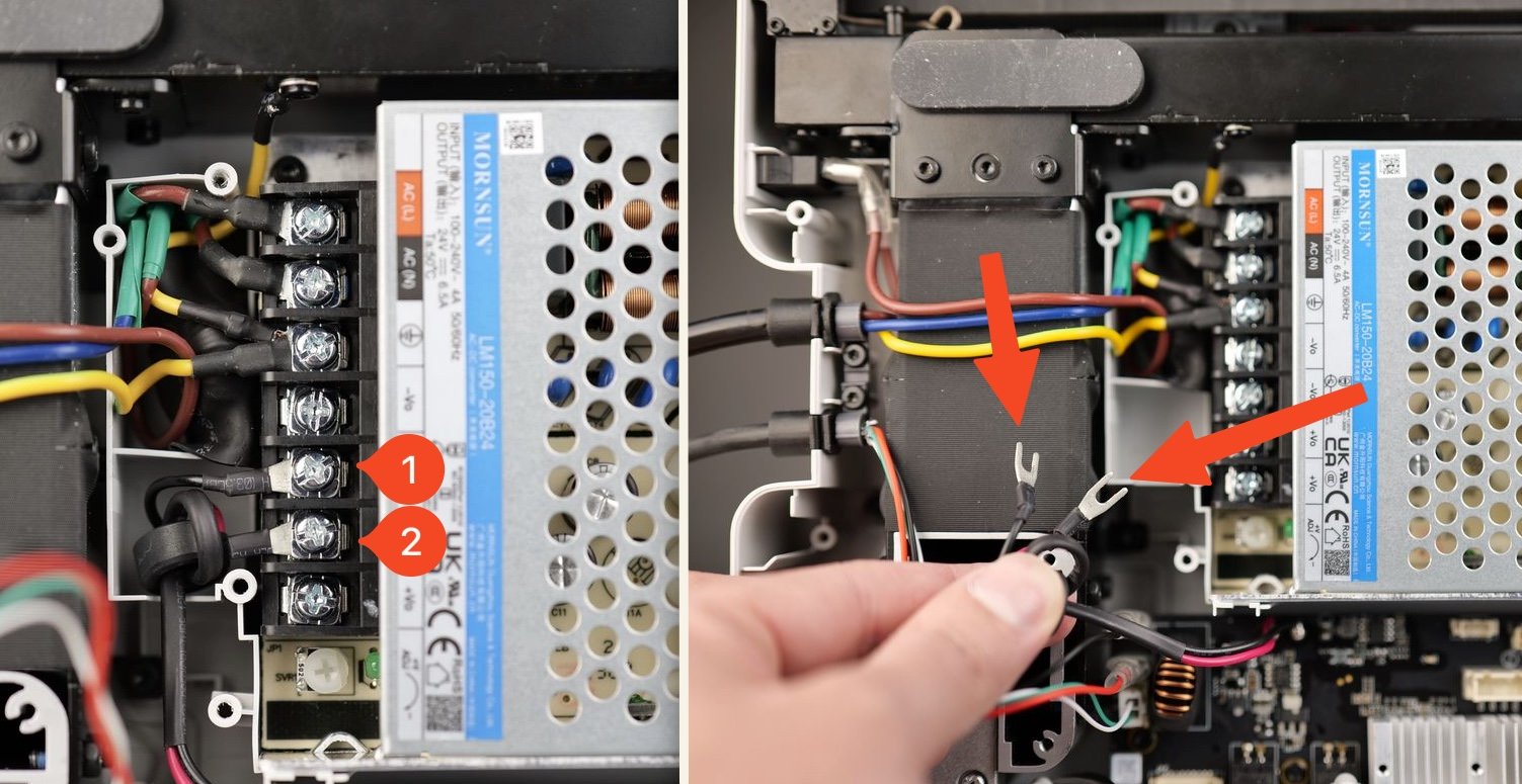
8. Remove the Mainboard wires from the power supply
Loosen the power terminal screws listed in the image below.
Simply make them loose and avoid removing them completely, as it will be easier to re-install everything back in place in the next steps.
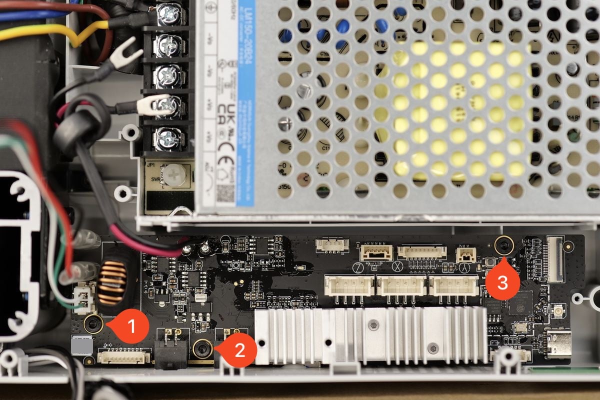
9. Remove the Mainboard screws and pull out the board
You can now remove the three screws holding the board in place.
Gently pull the board towards you to remove it from the printer.
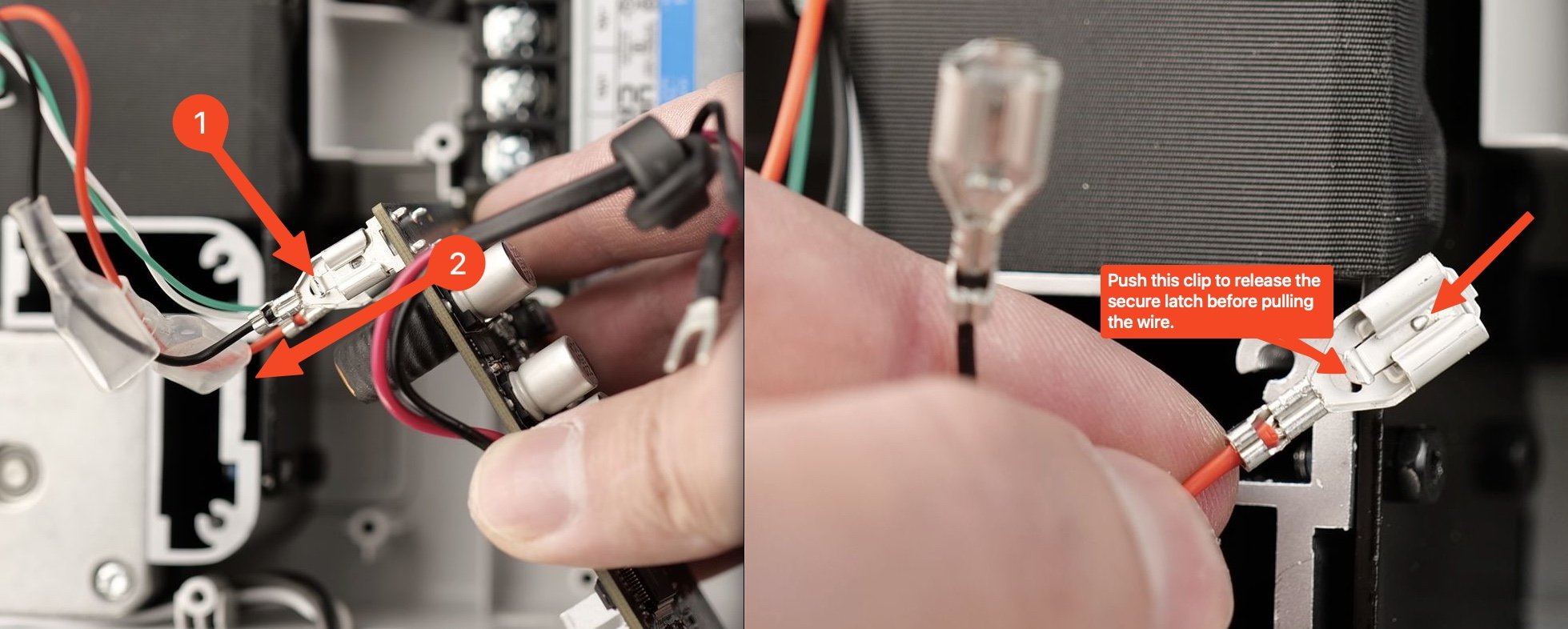
10. Remove the heatbed cable wires from the Mainboard
The final step in the removal of the Mainboard is to remove the heatbed cable wires from it.
The wires have a secure latch to hold them well-connected, so you will need to push on the small metallic clip when pulling the wires.
The Mainboard is now removed.
Steps to install the new Main Controller Board
1. Install the new Mainboard
Before you start the procedure, please take a picture of the QR code located on the back side of the board.
You will need it after the replacement is completed.
The content of this QR code is the complete machine SN serial number, which is used to register the device after replacing the mainboard.
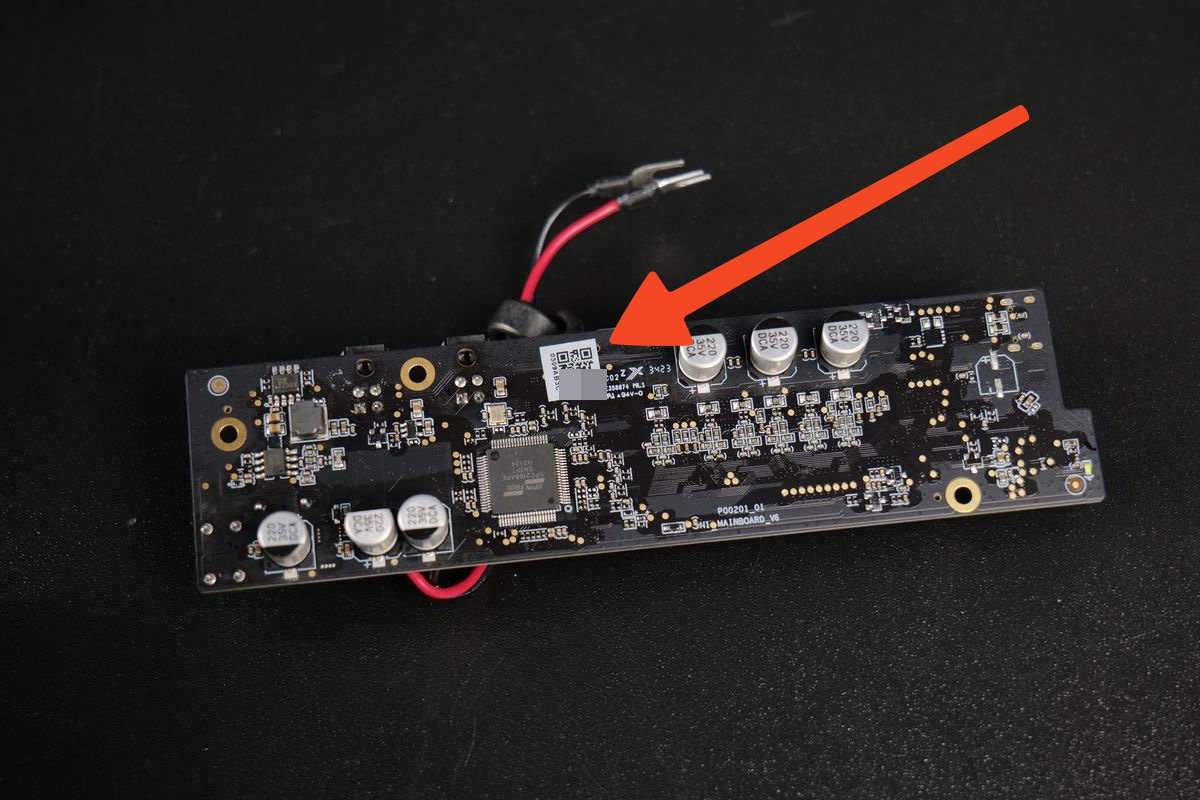
Proceed to install the new Mainboard and attach it with the three screws to the printer frame
2. Re-connect the heatbed cables to the Mainboard
Carefully re-connect the heatbed wires to the Mainboard. The Black wire is on the top, the Red wire is on the bottom.
Push the rubber insulation over the heatbed wire connectors, then re-connect the thermistor cable.
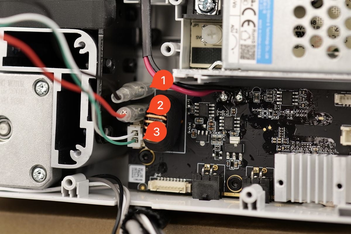
3. Re-connect the Mainboard power terminal wires
Carefully re-connect the power terminal wires as shown below and tighten the screws.
The wire information is as follows:
1. -V Mainboard Wire (Black)
2. +V Mainboard Wire (Red)
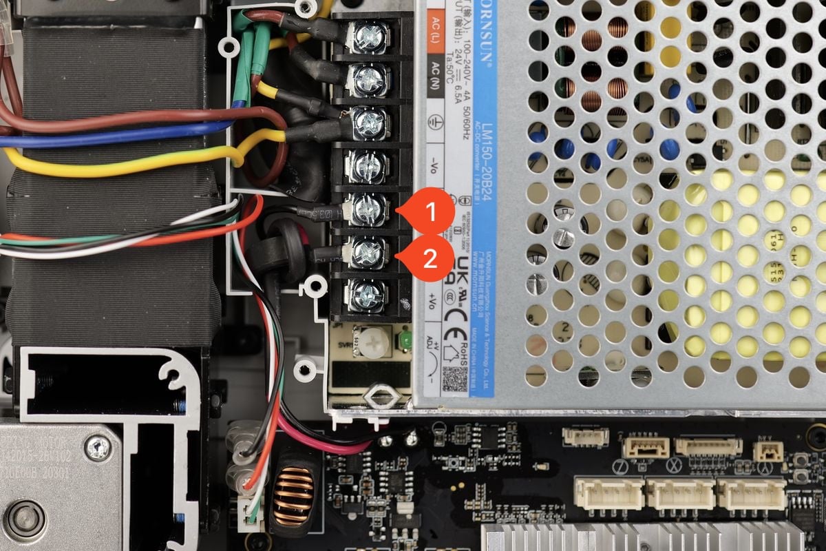
IMPORTANT
After installing all the wires as shown in the image below, ensure there is no movement and all the wires are fixed in place
4. Install the screws holding the plastic wire cover in place.
Arrange the wires coming from the heatbed cable and power cable as shown in the image, then re-attach the plastic cover back to the printer using the three screws
These screws will be threaded inside plastic standoffs. Avoid over-tightening them as you can damage the plastic threads.
5. Re-connect the remaining Mainboard cables
You can now re-connect the remaining Mainboard cables.
1. Z-axis motor
2. X-axis motor
3. Y axis motor
4. Eddy Sensor
5. Live View Camera
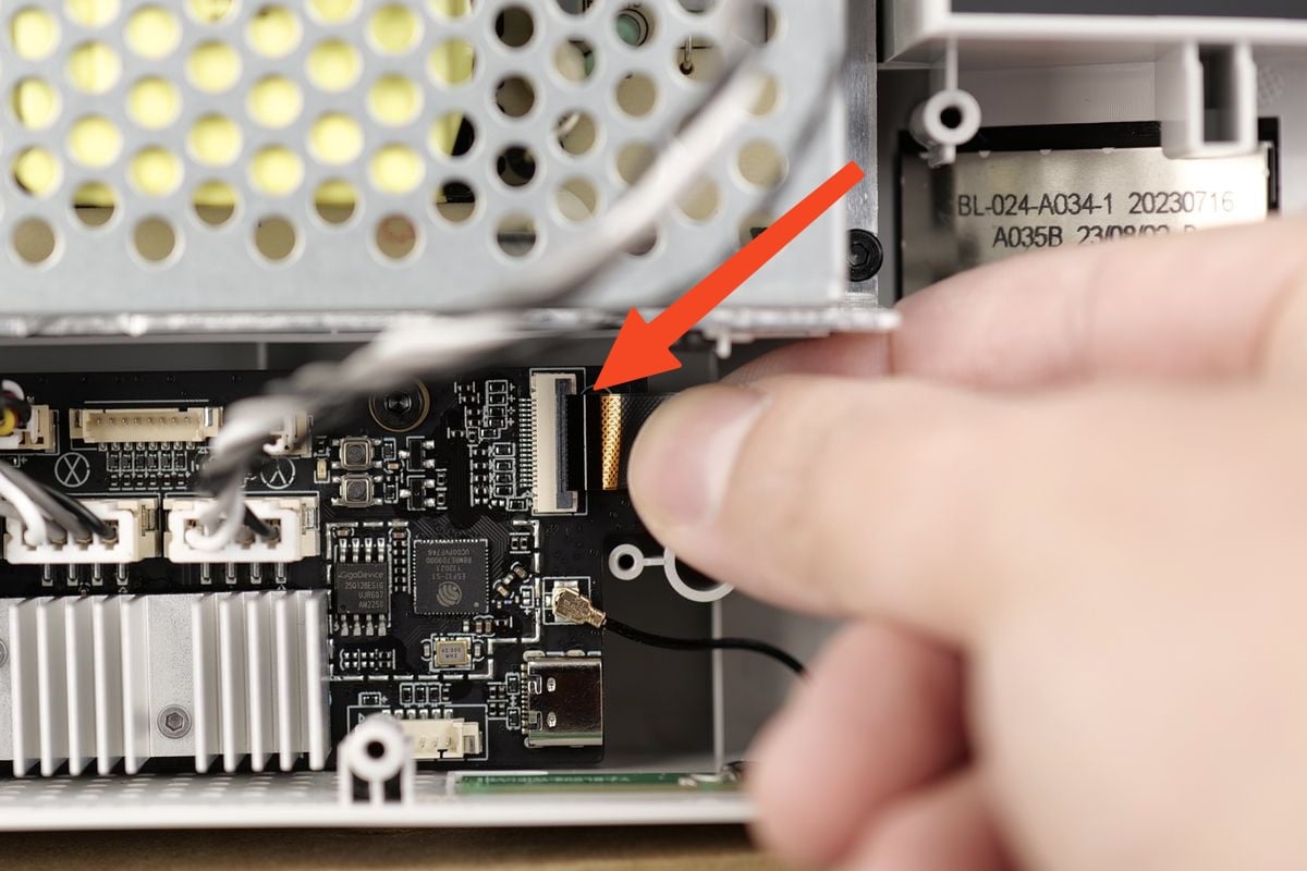
6. Re-connect the ribbon cable of the Touchscreen
Gently re-connect the ribbon cable, ensuring the white line aligns to the outline marked on the board.
When everything looks good, simply flip the clip towards the right to lock the ribbon cable in place.
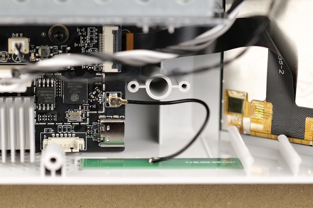
7. Re-connect the the Wi-Fi Antenna connector
Gently re-connect the round Wi-Fi antenna connector to the Mainboard. Take extra care when installing it.
The Wi-Fi antenna connector has a very small pin on the middle which can be damaged if the connector is not carefully aligned.
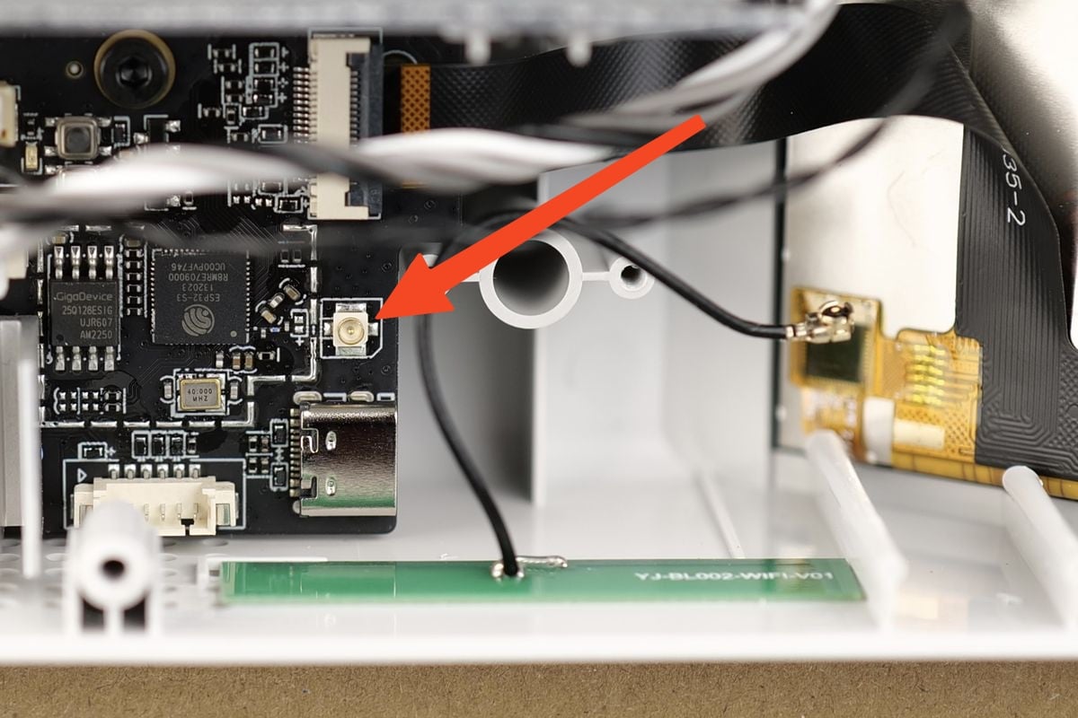
If everything is carefully aligned, the Wi-Fi antenna cable will clip in place, and look like this:
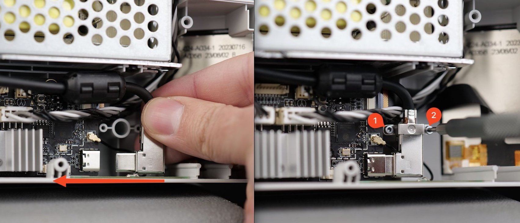
8. Connect the USB C cable and re-attach the bracket
Carefully route the USB cable towards the USB header on the board, and re-install it as shown below.
Then, re-attach the metallic bracket with the screws we removed before.
9. Install the Mainboard fan
You can now install the Mainboard fan connector to the Mainboard
Next, attach the fan to the Mainboard heatsink using the two screws.
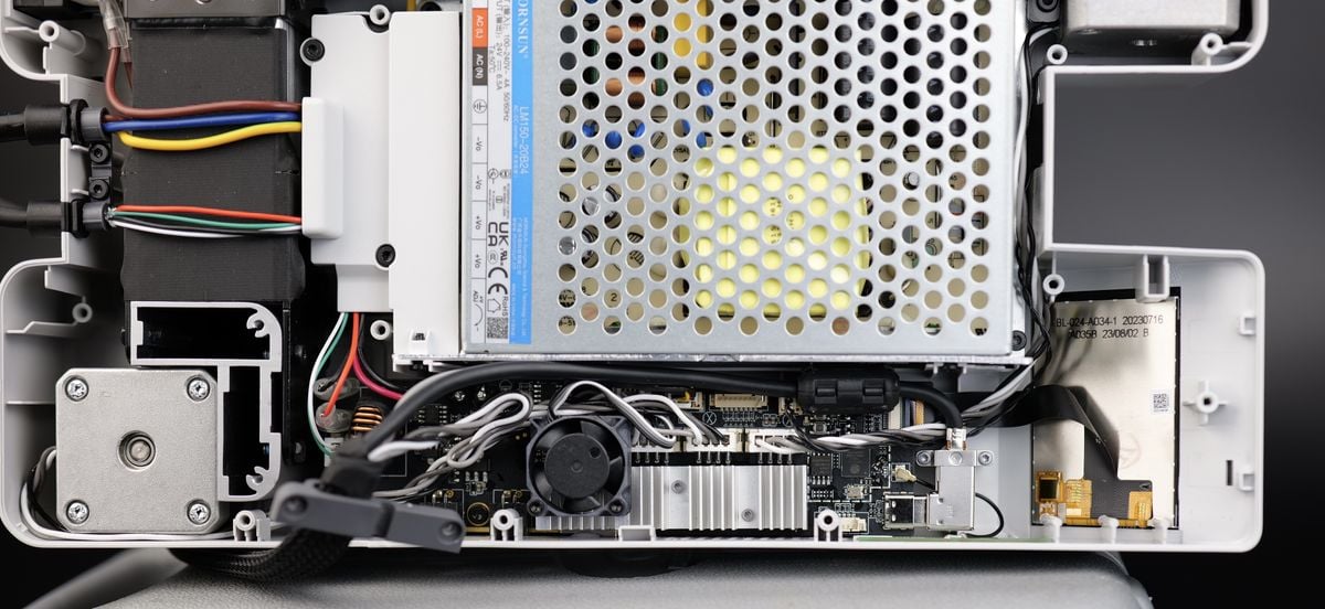
10. Perform some wire management
Before putting the bottom cover back in place, ensure that the Mainboard wires are routed correctly, so they do not interfere with the Mainboard fan, as shown in the image below.
11. Install the back cover
You can now proceed with installing the bottom cover back to the printer.
Start by tightening screws 15 and 16 to ensure the side wire loom sits correctly.
Then, proceed with installing the other remaining screws, while ensuring you do not over-tighten them.
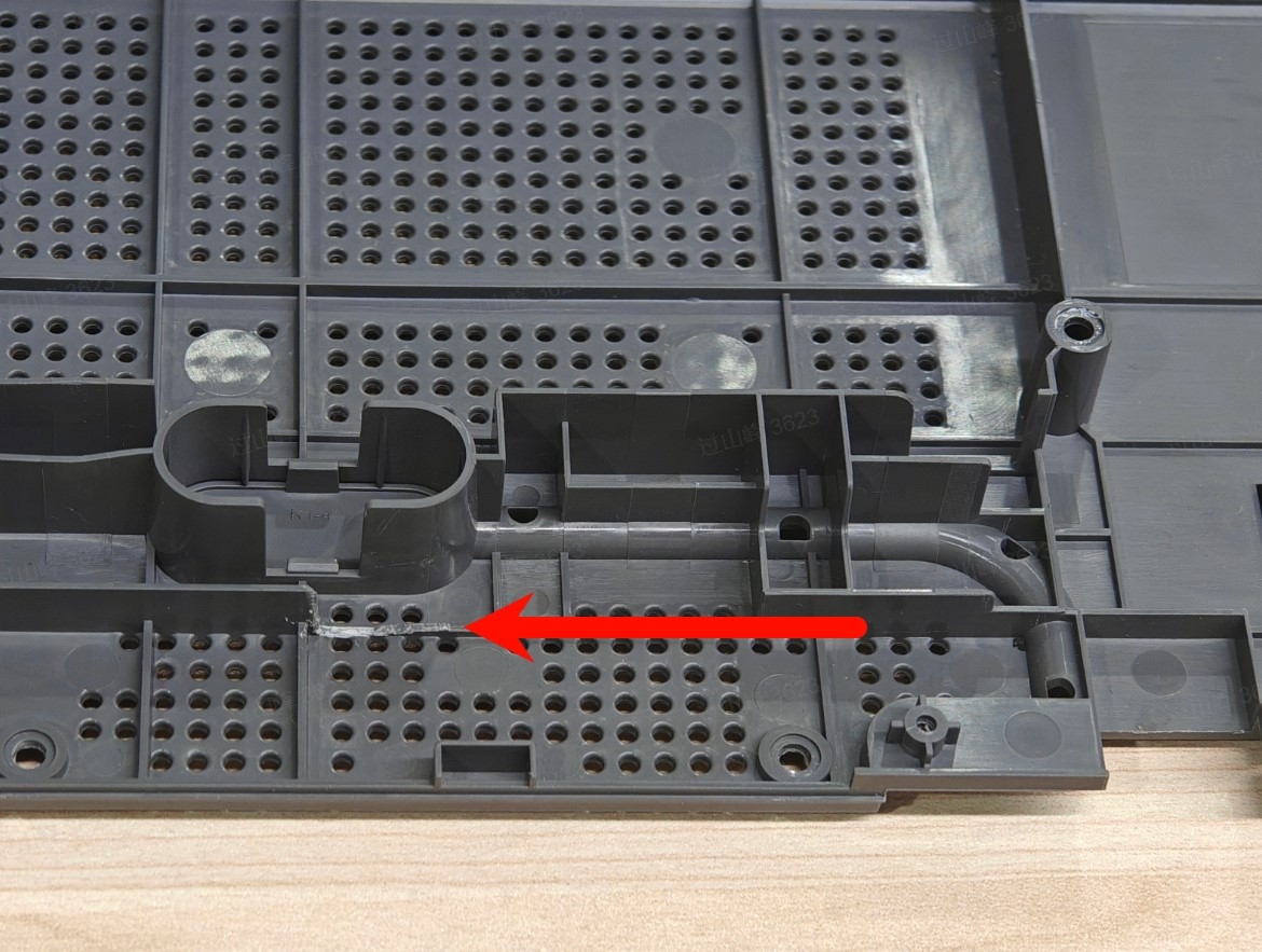
Due to changes in the fan placement on the updated 2025 mainboard, the older version of the A1 mini back cover may not fully close during installation.
As shown in the image below, you will need to manually trim the marked area to ensure the back cover can be properly closed.
Verify the functionality
To ensure everything works as expected, turn on the printer and perform a homing procedure.
Try to home the axis, and confirm the temperatures are correctly displayed on the screen.
If everything is confirmed to be working, this confirms the Mainboard installation was correct.
Check the indicator lights on the control board
Normal State: the MC board and AP board are integrated into the mainboard
The MC board flashes green once every 5 seconds
The AP board has 1 green indicator light that flashes once per second
Printer SN Registration
After this procedure is completed, the printer will have its original Serial Number, and you will be able to bind it to your account.
Important Note:
Once the new serial number (SN) is successfully registered, the old SN will be invalidated, and the old AP board can no longer be registered or bound.
For machines that have had the AP board replaced, as the new SN is not registered, binding cannot be performed. We recommend skipping the binding process during the initial startup to test if the replacement fixed the problem (unless you are troubleshooting network issues).

Calibration step after the operation
A full calibration is required after the Main Controller Board replacement procedure.
Potential problems and solutions
If you encounter problems during the installation of a new Motherboard, please check the potential problems and solutions listed below:
The printer doesn't power on
Confirm the Motherboard power wires are installed correctly, as shown in Step 3. Re-connect the Mainboard power terminal wires
The heatbed temperature is not reported / shows 0C
Check the heatbed cables shown in Step 2 Re-connect the heatbed wires, and confirm the Green and White wire connector is fully inserted in the Motherboard.
The heatbed is not heating
Check the heatbed cables shown in Step 2 Re-connect the heatbed wires, and confirm the Red and Black wires are fully inserted in the Motherboard.
One of the axis is not working
Check the motor wires and confirm they are installed correctly, as shown in Step 5. Re-connect the remaining Mainboard cables
The printer cannot be connected to your Bambu Lab Account
The new board will need to be registered by
Customer Support.
To do so, provide a picture of the Main Controller board QR code (the one located on the back side of the board) and wait for a confirmation.
A1 Mini Mainboard Connectors
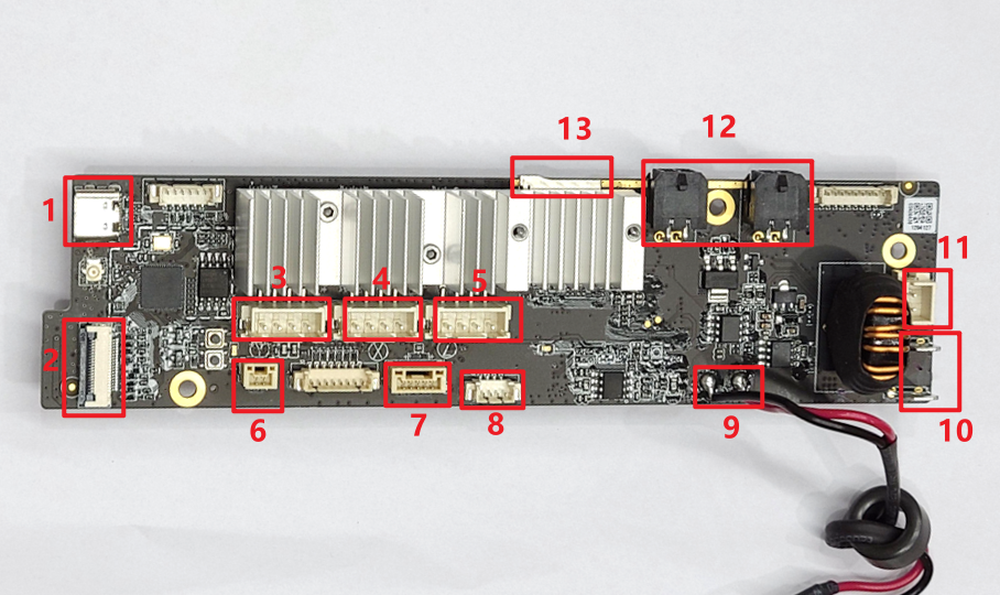
1.USB-C to TH Board Connector
2.Touchscreen Connector
3.Y-Motor Connector
4.X-Motor Connector
5.Z-Motor Connector
6.Eddy Sensor Connector
7.Live View Camera Connector
8.MC Board Cooling Fan Connector
9.Power Input Wires
10.Power Output Connectors for Heatbed
11.Heatbed Signal Cable Connectors
12.AMS Lite Connectors
13.SD Card