


Bambu Lab for H2C Induction Heating Assembly
Couldn't load pickup availability
Use this text to encourage communication or promote sharing on social networks.
The Hotend Heating Assembly is designed to heat the hotend and enable quick hotend replacement. The heating assembly secures the hotend with a clamping mechanism, allowing easy removal for maintenance or replacement.
Installation
Learn more about the Hotend Heating Assembly on Bambu Lab Wiki.
In the Box For Hotend Heating Assembly - Left
- Hotend Heating Assembly - Left*1
- Baffle Plate*1
- M2.5-7 Screw*4
- M1.6-4 Screw*2
In the Box For Hotend Heating Assembly - Right
- M3x5 Screw*2
- M3x14 Screw*2
- Lubricant Oil *1
Compatibility
H2C and H2C Laser
H2C Induction Heating Assembly
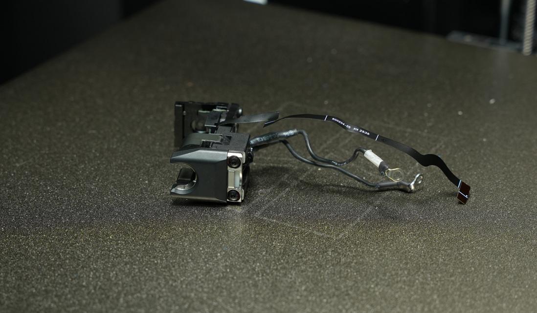
The Induction Heating Assembly - Right is the core functional module that enables non-contact rapid heating of the hotend. It features an integrated induction coil that generates eddy currents inside the hotend assembly through electromagnetic induction, allowing for fast temperature rise. Additionally, the module incorporates a temperature acquisition interface and a Hall sensor to facilitate temperature data transmission and detect the installation status of the hotend.
When to Use this Guide
The induction heating component is damaged
Bambu Lab technical support recommends replacement
Required Tools and Materials
New induction heating assembly
H1.5 and H2.0 Hex wrenches
Screw box (optional)
This replacement process involves many screws, so it’s a good idea to prepare a small storage box or organizer beforehand. This will help you keep the screws sorted and make reassembly easier later.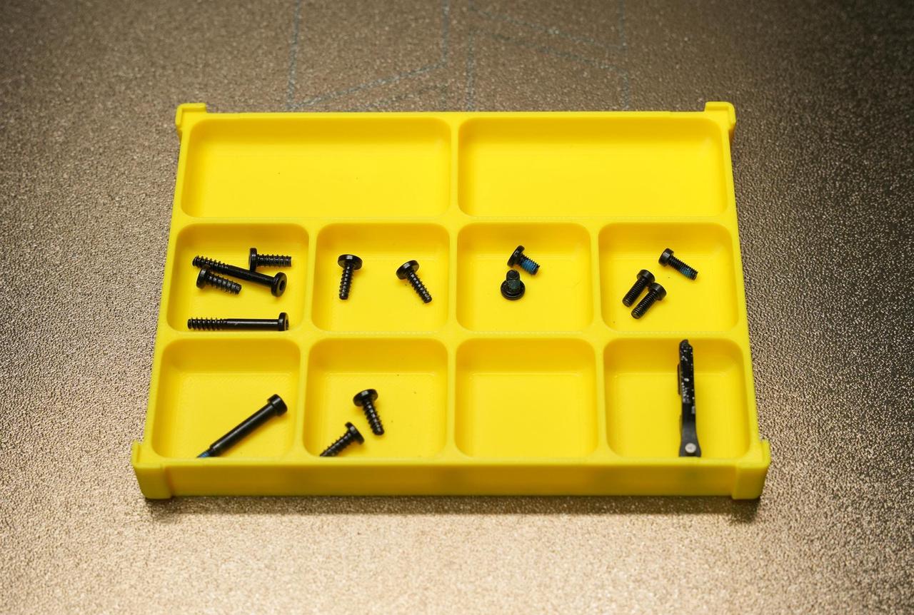
Safety Warning
IMPORTANT!
It's crucial to power off the printer before conducting any maintenance work, including work on the printer's electronics and tool head wires. Performing tasks with the printer on can result in a short circuit, leading to electronic damage and safety hazards.
During maintenance or troubleshooting, you may need to disassemble parts, including the hotend. This exposes wires and electrical components that could short circuit if they contact each other, other metal, or electronic components while the printer is still on. This can result in damage to the printer's electronics and additional issues.
Therefore, it's crucial to turn off the printer and disconnect it from the power source before conducting any maintenance. This prevents short circuits or damage to the printer's electronics, ensuring safe and effective maintenance.
Removing the Old Induction Heating Assembly
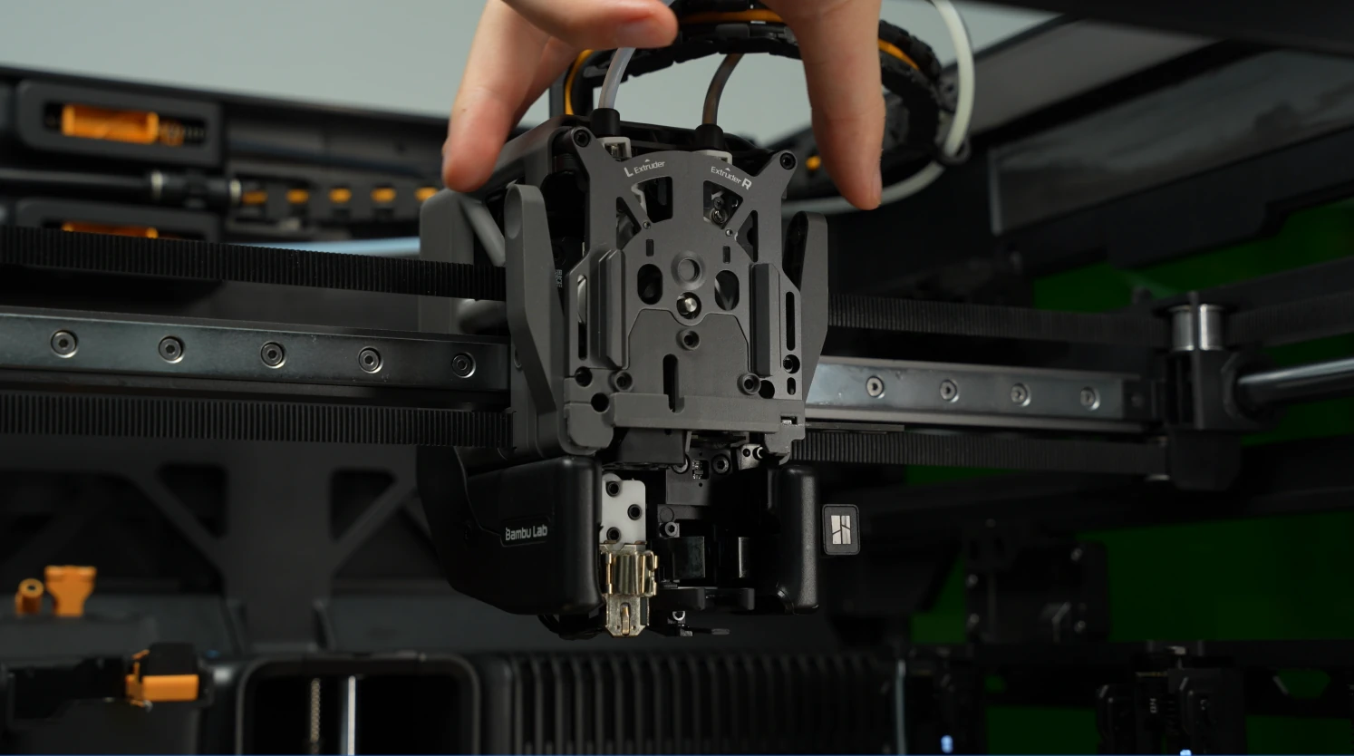
Step 1: Remove the Toolhead Enhanced Cooling Fan
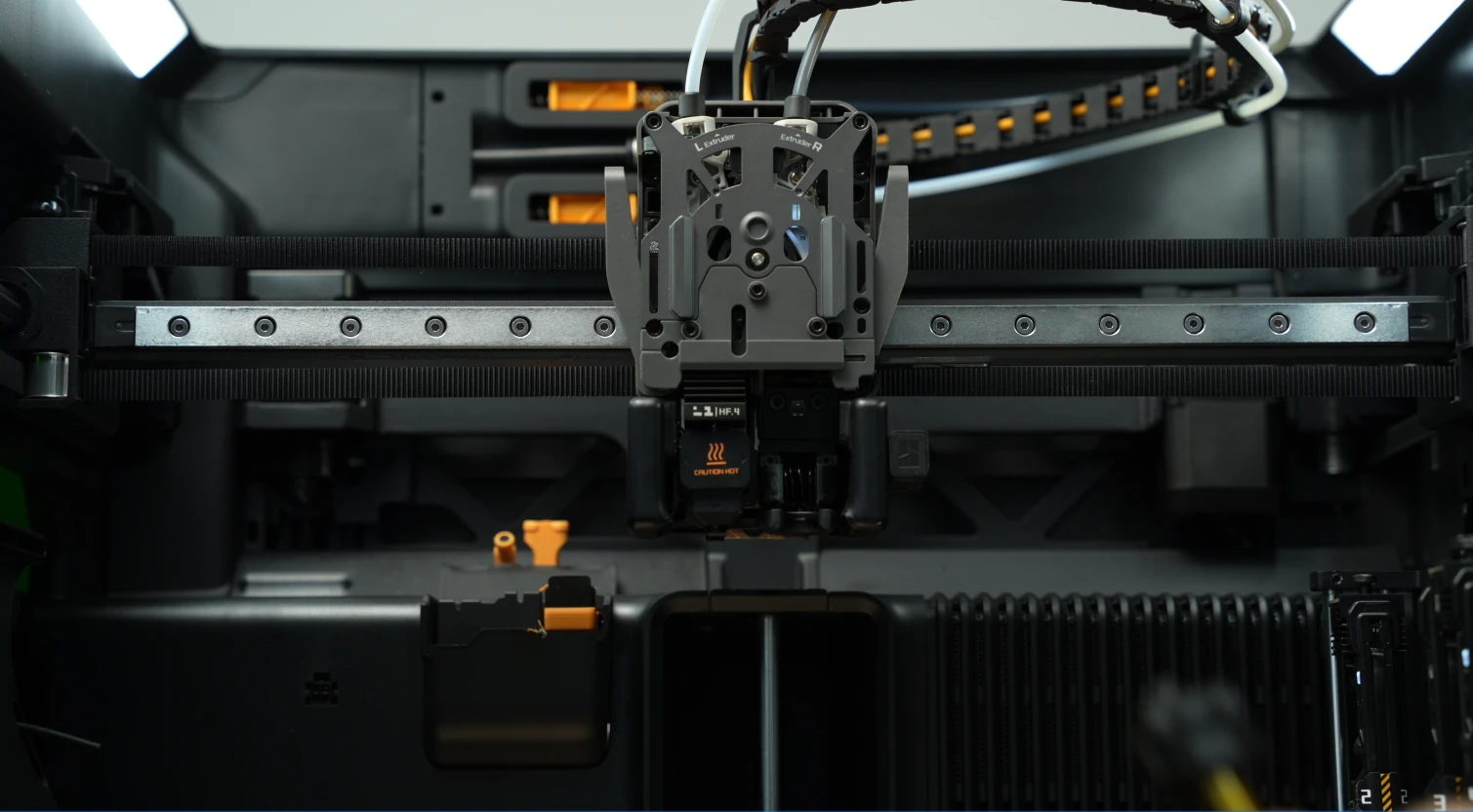
Step 2: Remove the Left and Right Hotends
Left nozzle: Remove the silicone sleeve, open the fixing clip of the nozzle assembly, and take out the left nozzle assembly.
Right nozzle: Pull the nozzle handle to the right to unlock, then remove the right nozzle assembly.

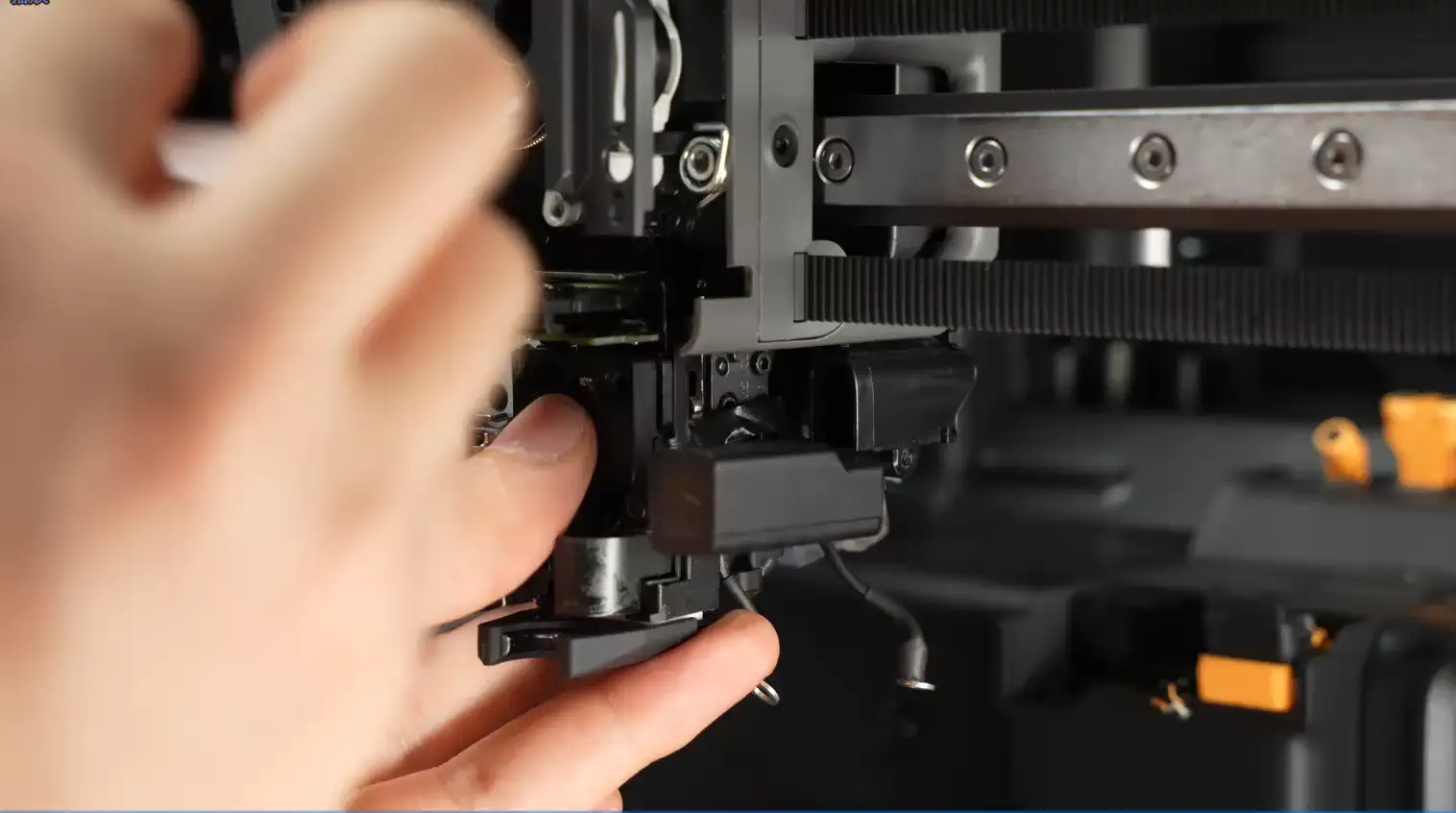
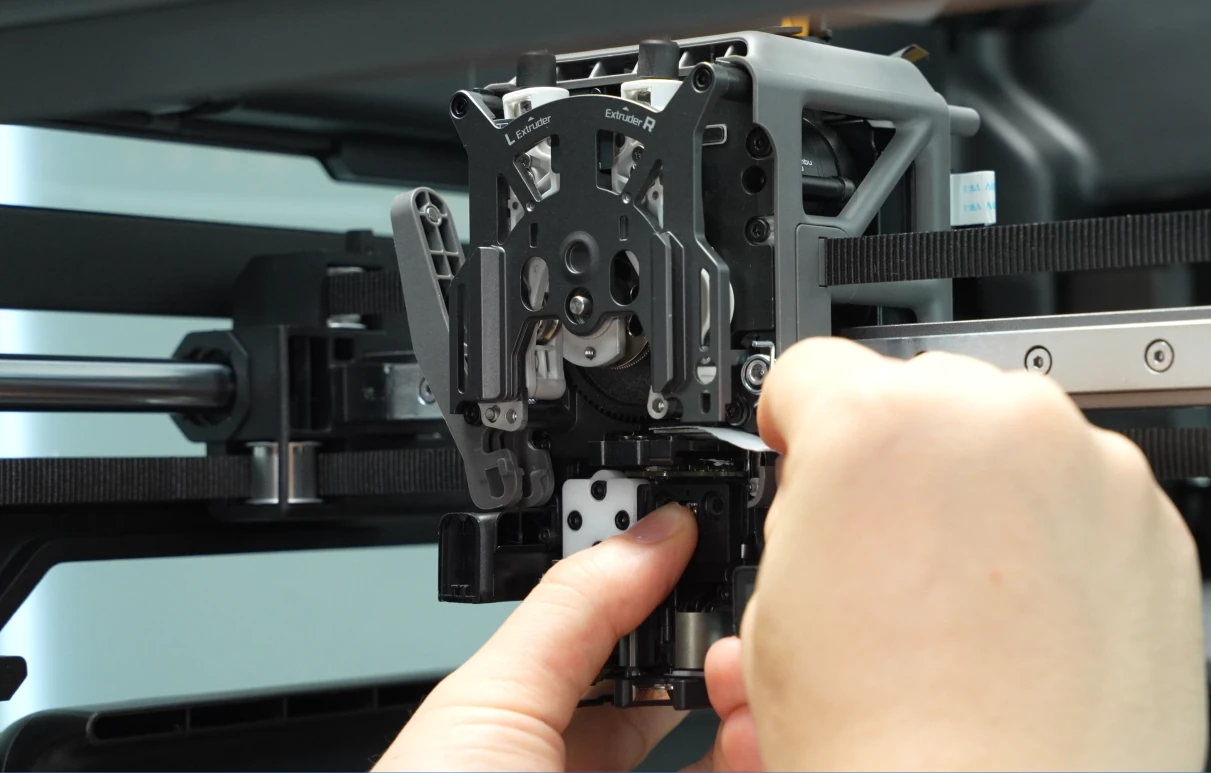
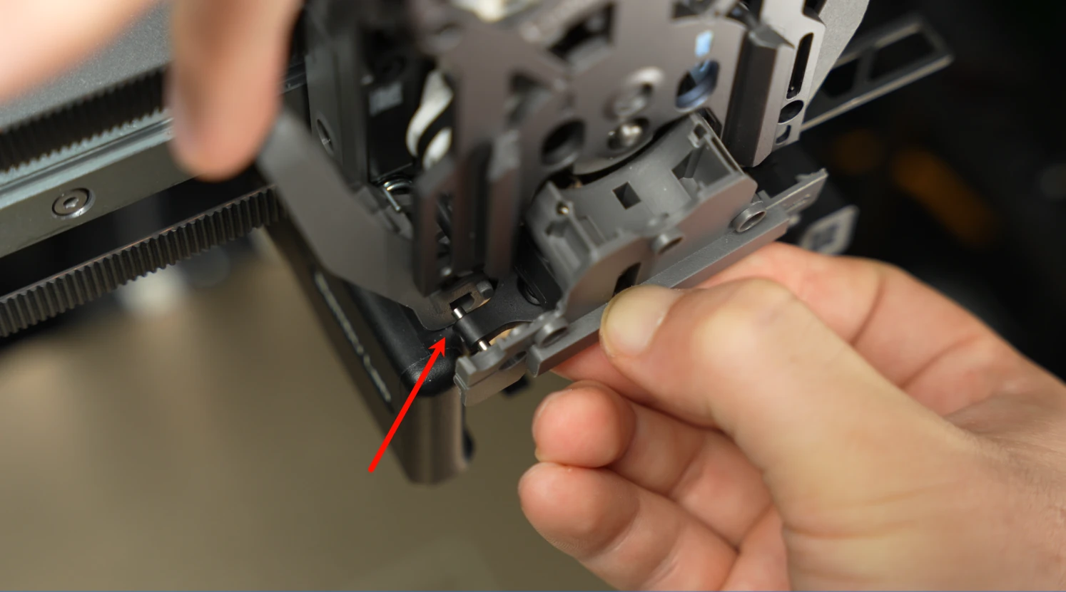
Step 3: Remove the Extruder Filament Guide Assembly
Use your fingers to press against the black nozzle connector from below,
while gently pressing the handle of the left cutter to dislodge the left cutter from the slot near the cutter screw.
 For detailed replacement steps, please refer to the wiki: Dual Extruder Filament Guide Replacement Guide for the H2C | Bambu Lab Wiki.
Step 4: Remove the Part Cooling Fan
For detailed replacement steps, please refer to the wiki: Replacing the H2C Part Cooling Fan.
Step 5: Remove the Hotend Fan Air Duct Outlet
Use an H1.5 hex wrench to remove the two fixing screws (M2×5). Hold the duct body securely with one hand, then pull it straight outward to remove the duct outlet.
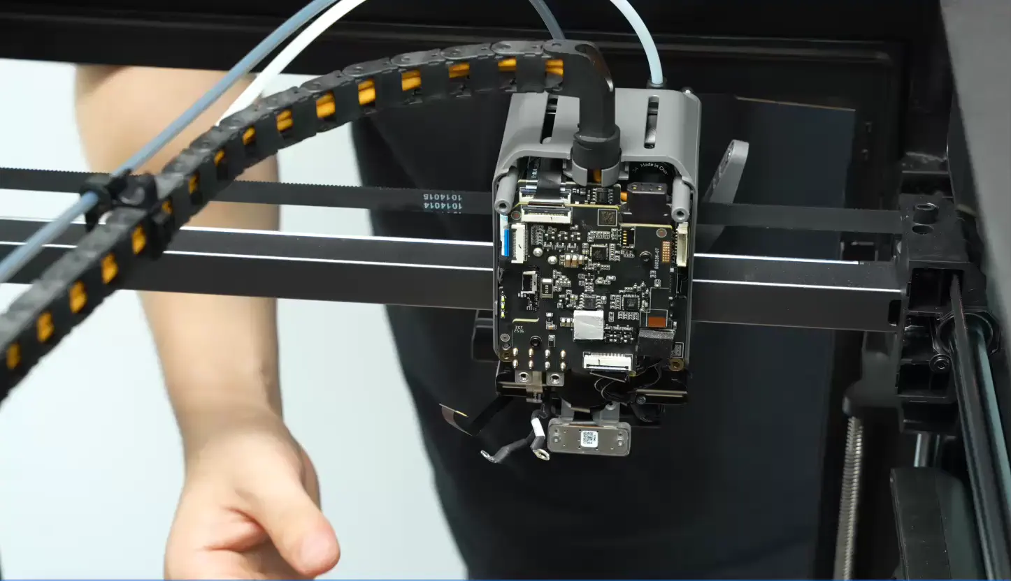
Step 6: Remove the Induction Heating Assembly
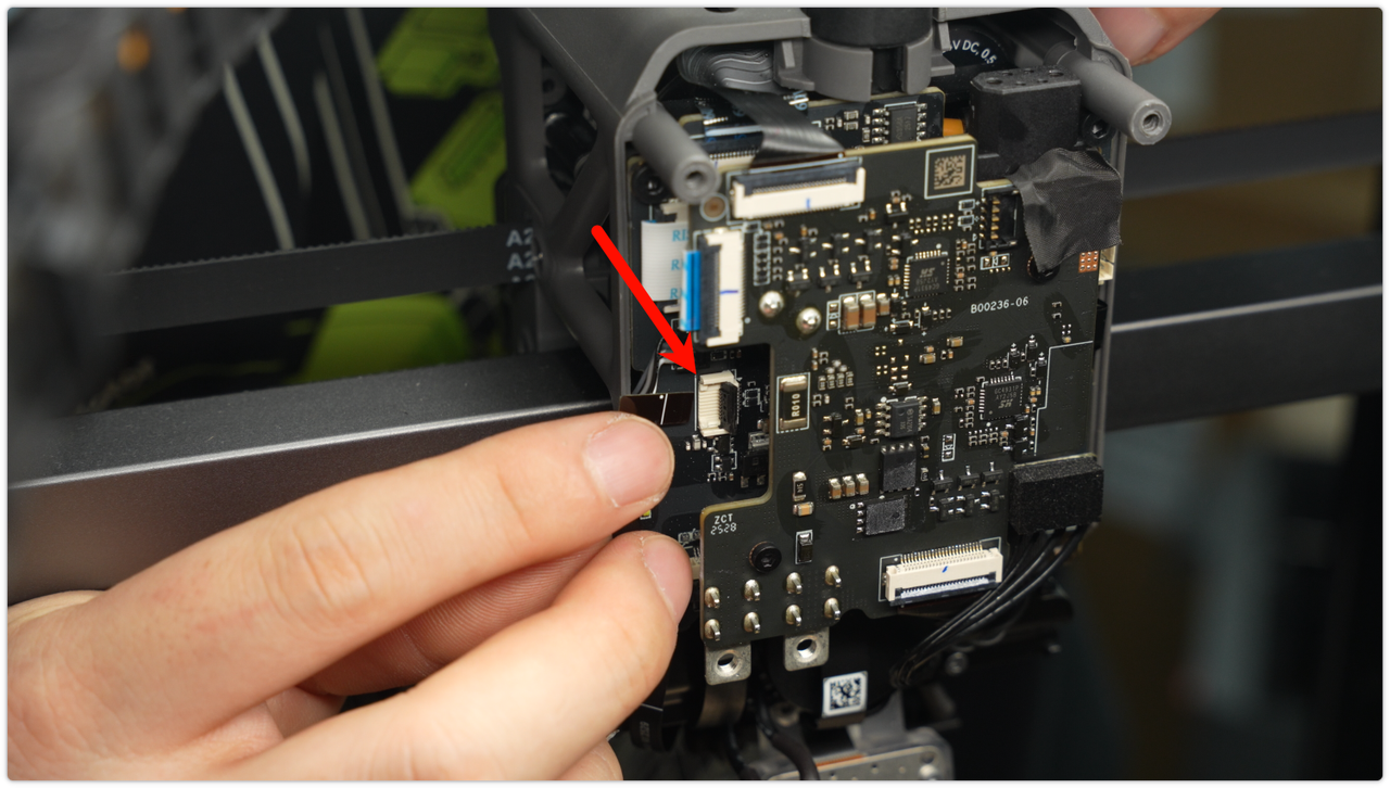
Open the signal cable clip of the induction heating assembly and disconnect the signal cable. Be careful not to pull it with excessive force.
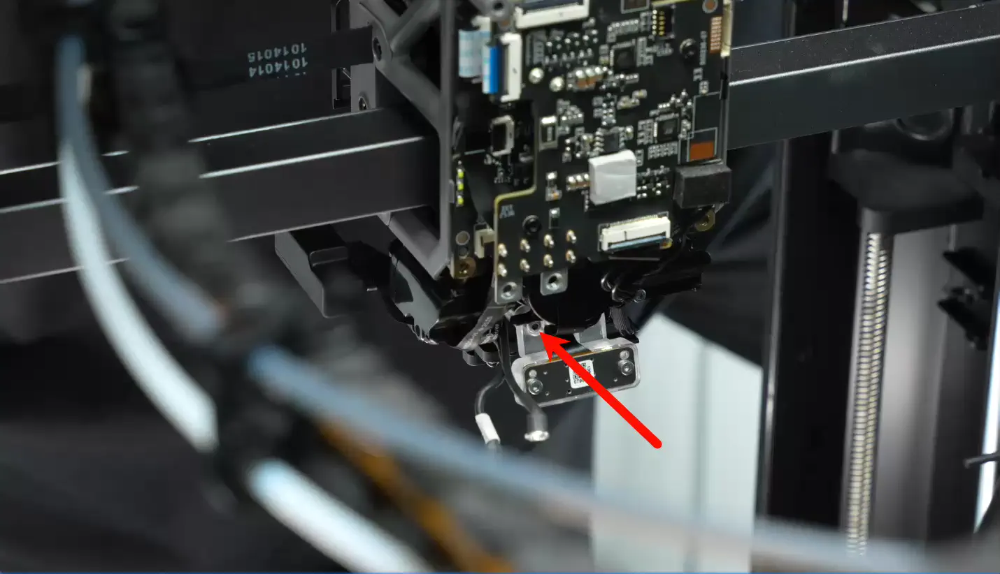
 Use an H2.0 hex wrench to remove the two fixing screws (M3*6), disconnect the power cord of the induction heating assembly, and pull it out of the cable slot.
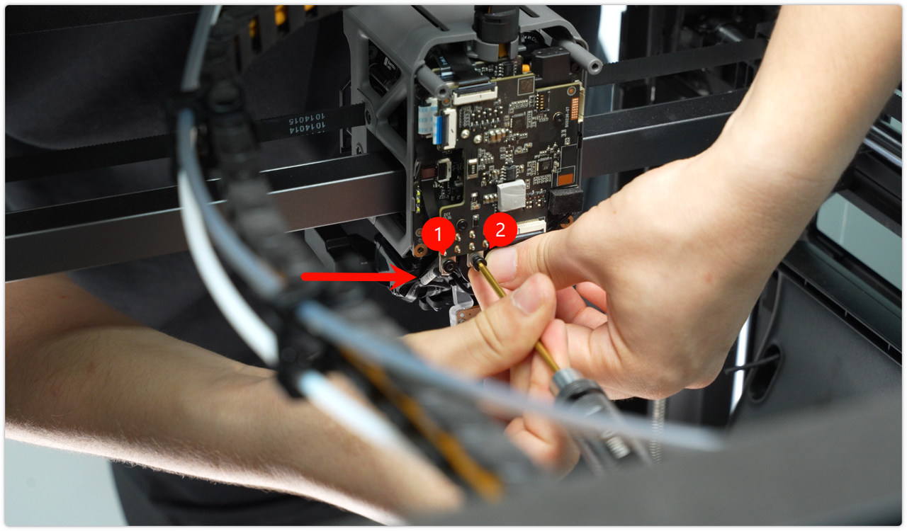
 Next, move to the front and use an H2.0 hex wrench to remove the two retaining screws (M3×12).
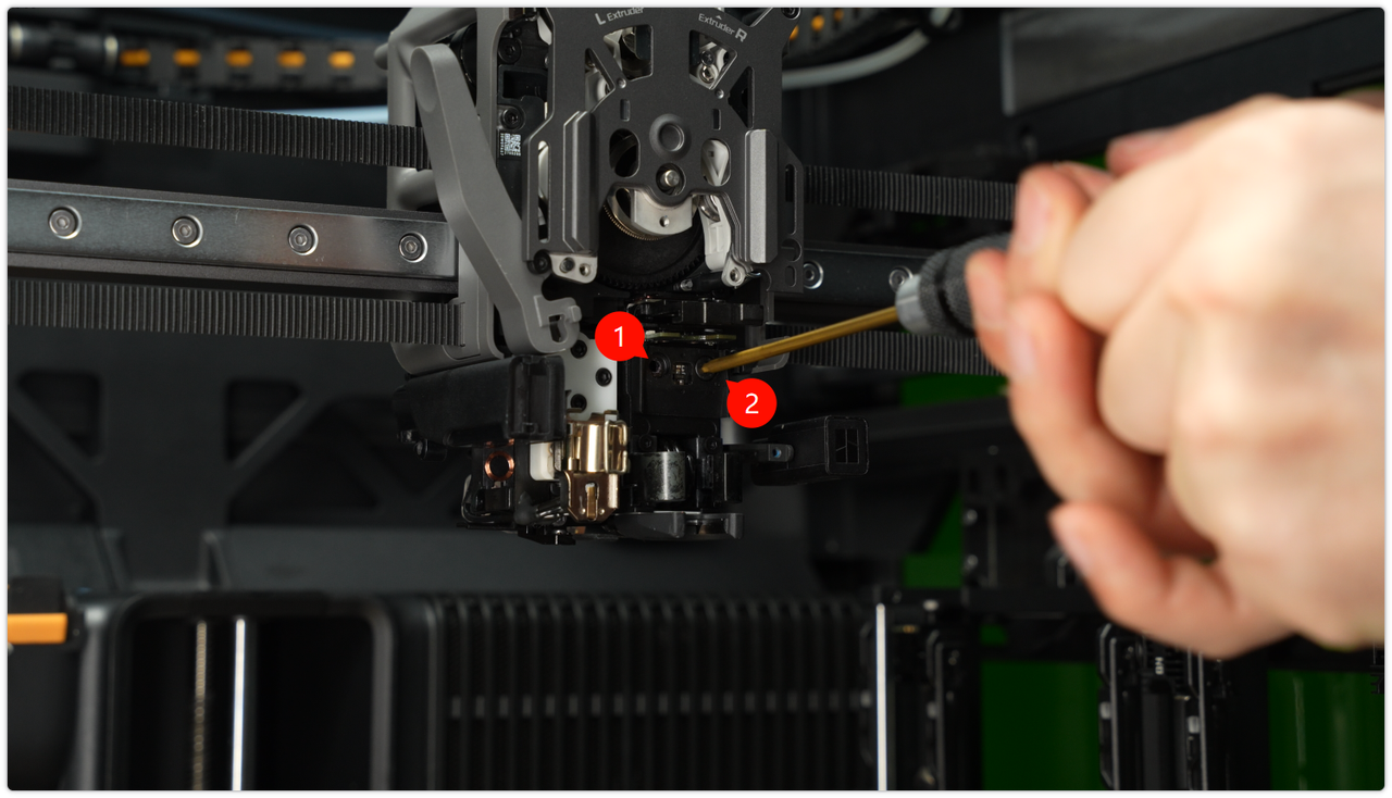
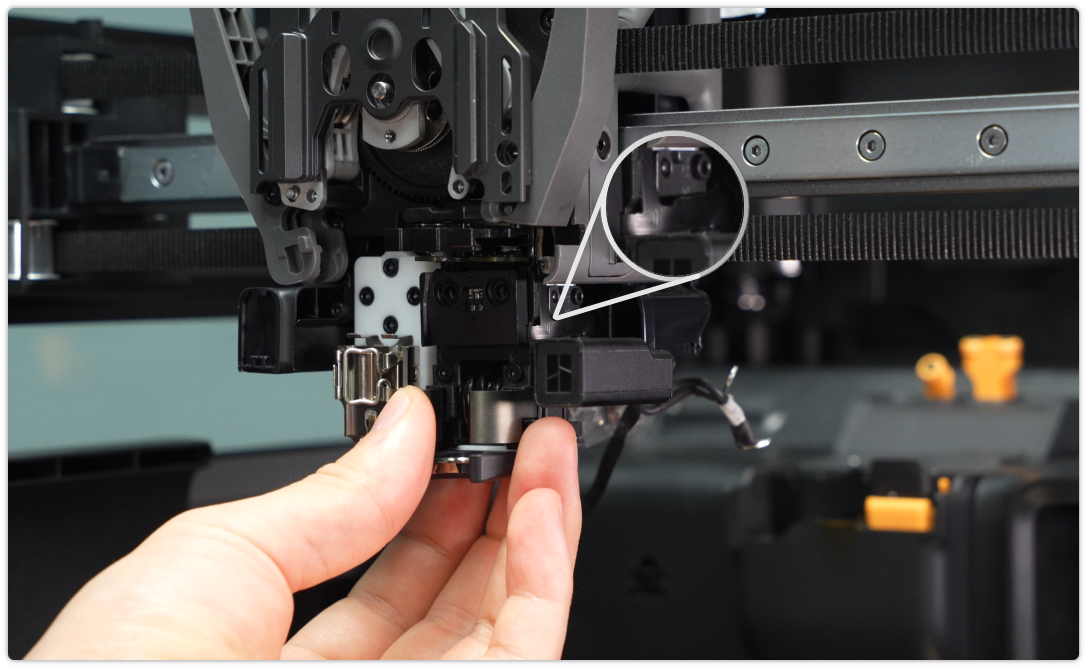
Slowly remove the induction heating assembly, supporting its body throughout the process to prevent the signal and power cables from being pulled or pinched. The side ribbon cable is coated with adhesive, so take extra care when removing it to avoid tearing the cable.
Installing the New Induction Heating Assembly
Step 1: Install the Induction Heating Assembly
To facilitate the installation of the heating assembly, adjust the cables to an overlapping (top and bottom) position before installation.

First, insert the signal wire of the induction heating assembly into the air duct outlet mounting position, and pass the power cable through the designated hole at the bottom of the component.
Note: Once the cables are in place, avoid pushing them upward with force, as this could damage the upper eddy current coil.
 Place a thin strip of A4 paper on top of the heating assembly to act as a cushion, preventing it from coming into direct contact with the top eddy current coil during installation.
After initially positioning the components, check the gap by sliding the A4 paper strip left and right. There should be slight resistance, with the gap maintained between 0.1–0.2 mm. Avoid making it too tight (which could pinch the coil) or too loose (which would exceed the gap standard).
After positioning the components, use an H2.0 hex wrench to install the two M3×12 fixing screws. To do this, first pre-tighten the screws, then tighten them evenly and symmetrically to ensure the components are mounted flat.

Use tweezers to straighten the signal cable of the heating assembly and guide it toward the rear of the device.
 Open the black clip on the signal interface, carefully insert the ribbon cable connector, and close the clip once you have confirmed that the connector is fully seated.
 Organize the power cables of the heating assembly and tuck them neatly into the designated cable slots, making sure that the cables with white labels are positioned on the outside.
Use an H2.0 hex wrench to install the two M3×6 retaining screws, making sure the cable with the white label is connected to the left-side connector. After connecting, gently pull the cable to confirm it is secure.
Note: After installation, ensure that the two cables do not touch each other to prevent a short circuit. The cable with the white label must be connected to the left-side connector.
Step 2: Install Hotend Fan Air Duct Outlet
Align the screws and positioning holes, insert the duct outlet, and ensure the positioning pin fits precisely into its hole. Then, use an H1.5 hex wrench to tighten the two M2×5 fixing screws to secure the duct outlet.

Step 3: Install the Extruder Filament Guide Assembly
 For detailed steps, please refer to this wiki: H2C Extruder Filament Guide Replacement Steps
Step 4: Install the Left and Right Hotends
Left nozzle installation : Place the left nozzle assembly into its corresponding mounting position, fasten the fixing buckle to ensure the nozzle is secure, and then reinstall the silicone sleeve onto the left nozzle.
 Right nozzle installation :
Ensure that the pull handle is pulled out, align the right nozzle assembly with its mounting position, and push it in. Press the pull handle to lock it in place, then gently shake the nozzle to confirm that it is secure and not loose.
For detailed steps, please refer to this wiki: H2C Induction Hotend Installation Guide
Step 5: Install Toolhead Enhanced Cooling Fan
 Verifying Functionality
Connect the power supply and turn on the printer. Heat the right nozzle and verify that it reaches the correct temperature.
Screw List
BT3x8 x 4pcs;
BT3x20 x 2pcs;
M2.5x7 x 3pcs;
BT2.6x8 x 2pcs;
M2×5 x 2pcs;
M3×6 x 2pcs;
M3x12 x 2pcs;