


Toolhead Carriage for Bambu-X2D
Couldn't load pickup availability
Use this text to encourage communication or promote sharing on social networks.
[Perfect Fit for X2D] Custom-designed for X2D, ensuring precise alignment and direct replacement without modifications.
[Stable X-Axis Movement] Reinforced aluminum alloy structure enables smooth, low-vibration toolhead motion for high-speed printing.
[Lightweight & Rigid] Optimized balance of light weight and high rigidity reduces inertia, improving precision and layer adhesion.
[Easy Installation] Complete pre-assembled kit includes all mounting hardware for quick, tool-free installation.
[Durable Construction]wear-resistant components withstand long-term use, ensuring consistent performance.
The toolhead carriage assembly consists of front and rear shells fixed on an aluminum sleeve, enabling X-axis movement via XY belt traction.
In the Box
- Toolhead Carriage Front Cover (Flow Blocker Assembly) *1;
- Rear Cover *1
-Cable Base *1
-Spring *4
-BT2x5 Screw *2
-BT3x8 Screw *8
Compatibility
X2D
Toolhead Carriage Replacement Guide for the X2D
In this wiki, you will learn how to replace the toolhead carriage on the X2D.
Toolhead CarriageThe toolhead carriage mainly consists of the front and rear covers of the carriage. It is installed on the graphite aluminum sleeve of the X-axis assembly and can move along the X-direction under the traction of the XY belt.
The accessory package includes:
Toolhead front carriage * 1 (including auxiliary hotend upgrade slider)
Toolhead carriage rear cover * 1
Flow blocker * 1 (spare)
Screws * 8
Springs * 4

Applicable Scenarios
Toolhead carriage assembly is damaged (e.g., stripped screw holes)
The lifting slider is malfunctioning
Required Tools and Materials
New toolhead carriage assembly
H1.5 allen key
H2.0 allen key
Remove the Toolhead Carriage Assembly
Step 1. Remove the Toolhead Housing and Hotend
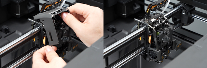
Step 2. Remove the Belt Retainer
Use an H2.0 Allen key to loosen the four tensioning screws (two turns are sufficient; there is no need to completely remove the screws) to release tension on the XY belt.

Use an H2.0 Allen key to remove the six screws securing the belt retainers on the toolhead, then remove the belt retainer blocks from both sides of the toolhead.

Step 3. Remove the Toolhead Carriage from the X-Axis
1.Please refer to remove the left and right filament cutter levers.

2.Disconnect the connectors on the TH board, then use an H1.5 Allen key to remove the four screws and detach the TH board from the toolhead.


3.Use an H2.0 allen key to remove the eight screws securing the carriage assembly.

4.Hold the toolhead front carriage by hand to prevent the four springs on top of it from falling off, then remove the rear cover of the toolhead block assembly.

If only the toolhead carriage rear cover is damaged or its screw holes are stripped, you can replace it with a new rear cover without further disassembly.
5.Then separate the toolhead front carriage from the upper linear rod to prevent the springs from detaching. Finally, remove the entire carriage front cover assembly from the X-axis.

Step 4. Disassemble the Toolhead Front Carriage Assembly
Disassembly here means removing the accessories installed on the toolhead front carriage from the carriage front cover so they can be installed onto the new toolhead front carriage.This process involves many steps. Please follow the disassembly order to avoid unnecessary removal steps.
1.Remove the heating assembly interface board and extruder connection board
Use an H1.5 allen key to remove the two screws fixing the hotend heating assembly connector bracket, remove the bracket, and disconnect all Others cables except for the toolhead front cover connecting cable.

Remove the extruder connection board and hotend heating assembly interface board.

2.Loosen the cables on both sides of the extruder
then remove the main hotend cooling fan. Use H2.0 and H1.5 Allen keys respectively to remove the upper and lower screws securing the main hotend cooling fan, and take off the fan.

3.Remove the Extruder Unit
Use an H2.0 Allen key to remove the three screws and detach the extruder from the toolhead front carriage. There is no need to remove the tape bundling the cables at this stage.

4.Remove Eddy Current Coils
Use an H1.5 allen key to remove the screws on the left and right Eddy Current Coils, and remove the Eddy Current Coils from the carriage front cover.

5.Remove hotend heating assembly
Remove the metal bracket under the auxiliary hotend Eddy Current Coils, use an H2.0 allen key to remove the fixing screws of the hotend heating Base Housing, and take off the two heating assemblies from the carriage front cover.

6.Remove the auxiliary hotend cooling fan
Use an H1.5 Allen key to loosen the screws securing the auxiliary hotend cooling fan and remove the fan. Then continue using the wrench to remove the two screws and detach the fan retaining plate.

7.Remove the toolhead camera
Use your thumb to pry up the top cover of the toolhead camera to loosen it;

Use an H1.5 Allen key to remove the screw securing the toolhead camera, then remove the camera. Be careful to avoid damaging the flat cable while loosening the screw.

8.Remove the flow blocker assembly
Use an H2.0 allen key to completely loosen the 3 screws fixing the flow blocker assembly, and remove the flow blocker assembly.

9.Remove extruder motor
Use an H2.0 Allen key to remove the two screws securing the extruder motor, detach the motor, and remove the bearing from the carriage front cover.

At this point, all components on the toolhead front carriage have been removed.
Install the Toolhead Carriage Assembly
Step 1. Assemble the Toolhead Front Carriage Assembly
1.Install extruder motor
Install the extruder motor onto the back of the toolhead front carriage and align the two screw holes, ensuring that the extruder motor’s ribbon cable is positioned on the right side. At the same time, transfer the extruder gear bearing from the old carriage front cover to the new carriage front cover.

2.Install the Flow Blocker Assembly
Installation Reminder:
When installing the flow blocker assembly, ensure that the lifting slider is pushed fully downward and the nozzle assembly lever is pushed fully to the right. Carefully identify the position indicated by the yellow arrow in the figure below. During installation, use these two positions to confirm proper alignment: the notch mark on the left must be positioned between the two protruding gears on the right.

Install the flow blocker assembly onto the toolhead front carriage. Following the installation guidance above, position the flow blocker assembly correctly. If the three screws interfere with the installation position, adjust them as needed, then pre-tighten the three screws one by one. After confirming that the assembly is properly aligned and not tilted, fully tighten the three screws.

3.Install the toolhead camera
Install the toolhead camera on the left side of the toolhead carriage, taking care to avoid the flat cable. Secure the toolhead camera with the two screws, then align the upper and lower camera covers and install the upper cover.


4.Install the Auxiliary Hotend Cooling Fan
Install the auxiliary hotend cooling fan retaining plate onto the toolhead front carriage. Refer to the figure below to ensure the retaining plate is oriented correctly, then insert the two screws without tightening them. Finally, install the auxiliary hotend fixing bracket under the retaining plate, then tighten the two screws to secure the fan.

5.Install the hotend heating assembly
Install the two heating assemblies onto the toolhead front carriage and secure each with three screws. Then reinstall the metal bracket for the auxiliary hotend eddy current coils onto the auxiliary hotend heating assembly.
6.Install the Eddy Current Coil
Install the two eddy current coils into their corresponding positions and secure each with two screws. The left coil uses a screw with a smaller nut.
If the metal locking tab used for cable management came off during disassembly, please reinstall it in the position shown in the figure below.

7.Install the Extruder Unit
Please check again and ensure that the gear assembly bearing is installed in the position indicated by the yellow arrow, and that the right Hall detection board assembly has slid into the extruder. Then install the extruder unit onto the toolhead front carriage, taking care to avoid all cables to prevent damage, and tighten the three fixing screws.

8.Install the main hotend cooling fan next to the left hotend heating assembly, then secure it with one large and one small silver screw. Arrange the cables properly to prevent damage.

9.Install the Heating Assembly Interface Board and Extruder Connection Board
Install the hotend heating assembly interface board and extruder connection board above the extruder.
Connect the cables to their corresponding connectors on the extruder connection board. After organizing the cables, connect the two hotend heating assembly cables, then install the hotend heating assembly connector bracket and secure it with two screws.
Step 2. Install the Toolhead Carriage Onto the X-Axis
1.Install the toolhead front carriage assembly from Step 1 onto the X-axis. First, position it against the lower graphite aluminum sleeve, then rotate the carriage front cover upward to engage it with the upper graphite aluminum sleeve while preventing the springs from falling off.

2.Hold the carriage front cover by hand and avoid the cables underneath. Install the carriage rear cover onto the X-axis, align the screw holes, then insert the eight screws in the order shown in the figure below.

3.Check and confirm that the toolhead cable connected to the TH board is properly connected. Then install the TH board onto the toolhead block rear cover, secure it with four screws, and reconnect the cables to the TH board.
4.Refer to install the left and right filament cutter levers.
Step 3. Install the Belt Retainer and Tighten the Belt
Attach the left and right synchronous belt retainer blocks to both sides of the toolhead and tighten the screws. To reduce the impact of belt tension, first pre-tighten the screws on both sides, then tighten them evenly together.
Move the toolhead through three full strokes in both the X and Y directions, then tighten the XY belt tensioning screws.
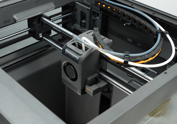
Step 4. Install the Hotend and Toolhead Housing
Verifying Success
✅ Connect the power and turn on the printer, run the full machine calibration process, and confirm that the calibration completes successfully.