


Neptune 3 4 Extruder Cables
Couldn't load pickup availability
Use this text to encourage communication or promote sharing on social networks.
Extruder cables assembly original kit for ELEGOO Neptune 3/4 Pro Max / Plus 3D Printers.
Neptune 4 plus/4 Max Print Head Cable Replacement
Step1:
Turn Off the power and remove the power card.

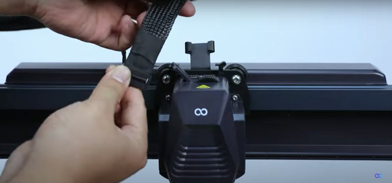
Step 2:
Press the “horn terminal ” on both sides with your hands and the print head cable will pop up automatically,

Step 3:
remove the print head cable from the cable fastener
Step 4:
Unplug the X-axis motor cable.

Step 5:
Unplug the X-axis motor cable.

Step 6:
Use a 2.5mm hex wrench to loosen a fixing screw of the cable clamp.
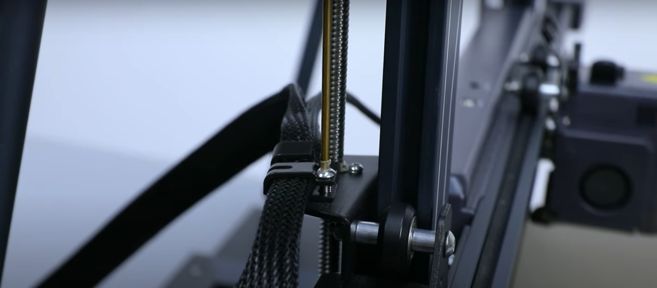
Step 7:
Remove the cable from the cable clamp.

Step 8:
Take out the cable fixing buckle.

Step 9:
Comb the cables and put them on the table.

Step 10:
Pull out the drawer box from the front of the printer.

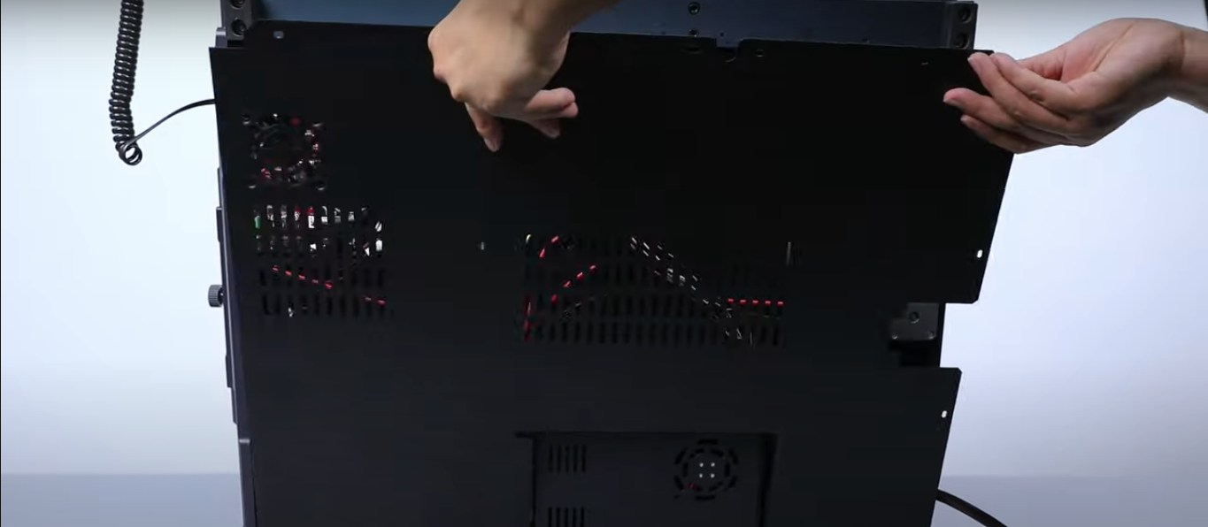
Step 11:
Use a 2.0mm hex wrench to loosen the 20 fixing screws on the bottom cover of the printer.


Step 12:
Use a 2.0mm hex wrench to loosen the 20 fixing screws on the bottom cover of the printer.

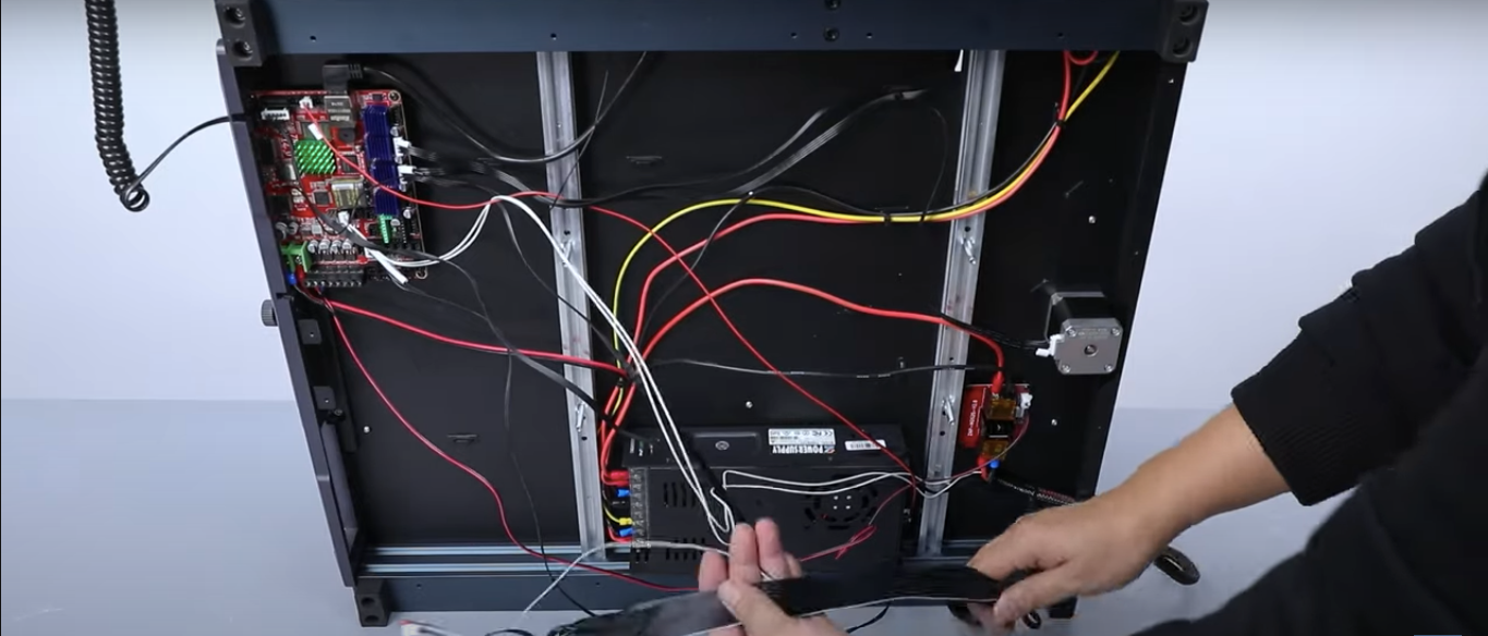
Step 13:
And then unplug the cable port of the motherboard cooling fan

Step 14:
And then unplug the cable port of the motherboard cooling fan.

Step 15:
Find the print head cable, and then remove the branch cable ports on the front end of the main cable from the motherboard.

Step 16:
Use a slotted screwdriver to loosen the two fixing screws of the “HE0”port.

Step 17:
Lift the lower right corner of the printer and remove the entire print head cable.
Step 18:
Take out the new print head cable.

Step 19:
Lift the lower right corner of the printer and place the print head cable underneath.(Be sure to reserve enough length)

Step 20:
Insert the cable ports of each branch on the front end of the print head main cable into the motherboard.
Note: According to the labels of each cable port to correspondingly locate the name of each port.

Step 21:
Insert the cable into the “HE0” port and use a slotted screwdriver to tighten the two fixing screws.

Step 22:
Comb the internal cables of the printer and fix them with five cable ties.

Step 23:
Take out the bottom cover, align it with the mounting position
Step 24:
And insert the motherboard cooling fan/cable into the motherboard’s FAN6 port.

Step 25:
Use a 2.0mm rex wrench to tighten the 20 fixing screws on the bottom cover of the printer.

Step 26:
Install the drawer box in front of the printer.

Step 27:
Take out the cable fixing buckle and align the buckle with the groove of the aluminum profile to fix the cable on the side.

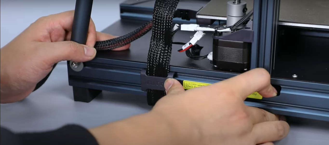
Step 28:
Take out the cable fixing buckle and align the buckle with the groove of the aluminum profile to fix the cable on the side.

Step 29:
Insert the X-axis motor cable into the port.

Step 30:
Insert the rear fan assembly cable into the port.

Step 31:
Put the cable into the cable fastener.

Step 32:
Move the print head and reserve enough cable length for the movement distance.


Step 33:
Sort out the print head cable and put the cable into the cable clamp.

Step 34:
Use a 2.5mm Allen wrench to tighten a fixing screw of the cable clamp.

Step 35:
Power on the printer.

Step 36:
Operate “Prepare -Temp-Nozzle Temperature ” on the touch screen and set the nozzle to heat to 210℃.

After observing that the printer nozzle is heating normally, it can be used normally.