


Dual Extruder Idlers and Filament Sensor for Bambu Lab
Couldn't load pickup availability
Use this text to encourage communication or promote sharing on social networks.
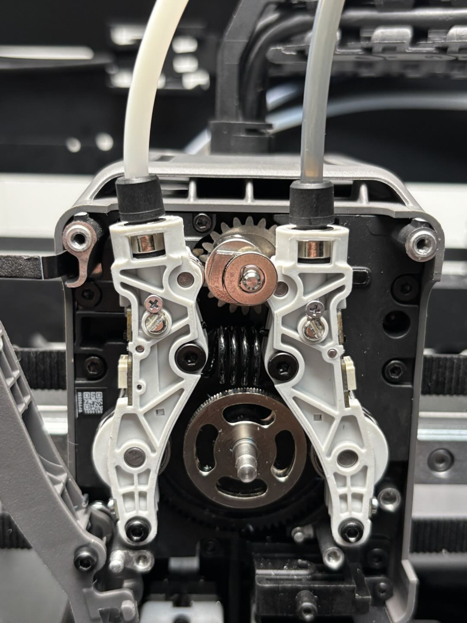
The Dual Extruder Idlers and Filament Sensor works together with the drive gear to grip and feed the filament, ensuring stable extrusion. In a dual extrusion system, it switches between different filament paths to support multi-color or multi-material printing.
【Original Dual Extruder Idler Assembly for H2D H2C】 This genuine factory part is the complete dual extruder idler and filament sensor assembly designed exclusively for Bambu Lab H2D and H2C. Package includes the extruder idler assembly, two BT2x5 screws, and two M2.5x19x5 screws for direct replacement.
【Integrated Filament Detection Sensor for Both Extruders】 Each side of this dual idler assembly features a Hall filament sensor that detects whether filament is properly loaded into the extruder. The sensors send real time status to the printer, preventing print failures caused by filament runout or loading errors.
【Precise Idler Wheels for Reliable Filament Feeding】 The idler wheels apply consistent pressure against the extruder gear to grip and feed filament smoothly. Worn or damaged idlers cause under extrusion, skipping, and failed prints. Replacing with this assembly restores proper filament grip and feeding force.
【Essential for Dual Extruder H2D and H2C Maintenance】 This idler assembly is a critical component of the H2D and H2C dual nozzle extruder system. When the idler wheels wear out or filament sensors fail, the printer may show filament jam errors or fail to detect filament. This replacement part restores full extruder functionality.
【Direct Replacement with Factory Spec Screws】 When your original dual extruder idler assembly is damaged or worn, this factory part is a direct drop in replacement. Installation follows the official Bambu Lab Wiki guide using H2.0 and H1.5 Allen keys. The included BT2x5 and M2.5x19x5 screws match factory specifications. No third party parts needed.
In the Box
- Dual Extruder Idlers and Filament Sensor*1
- BT2-5 Screw*2
- MG2.5-19.5 Screw*2
Compatibility
H2D and H2D Laser
H2C and H2C Laser
Replace H2D Dual Extruder Idlers and Filament Sensor
This article describes how to replace H2D Dual Extruder Idlers and Filament Sensor
Dual Extruder Idlers and Filament Sensor
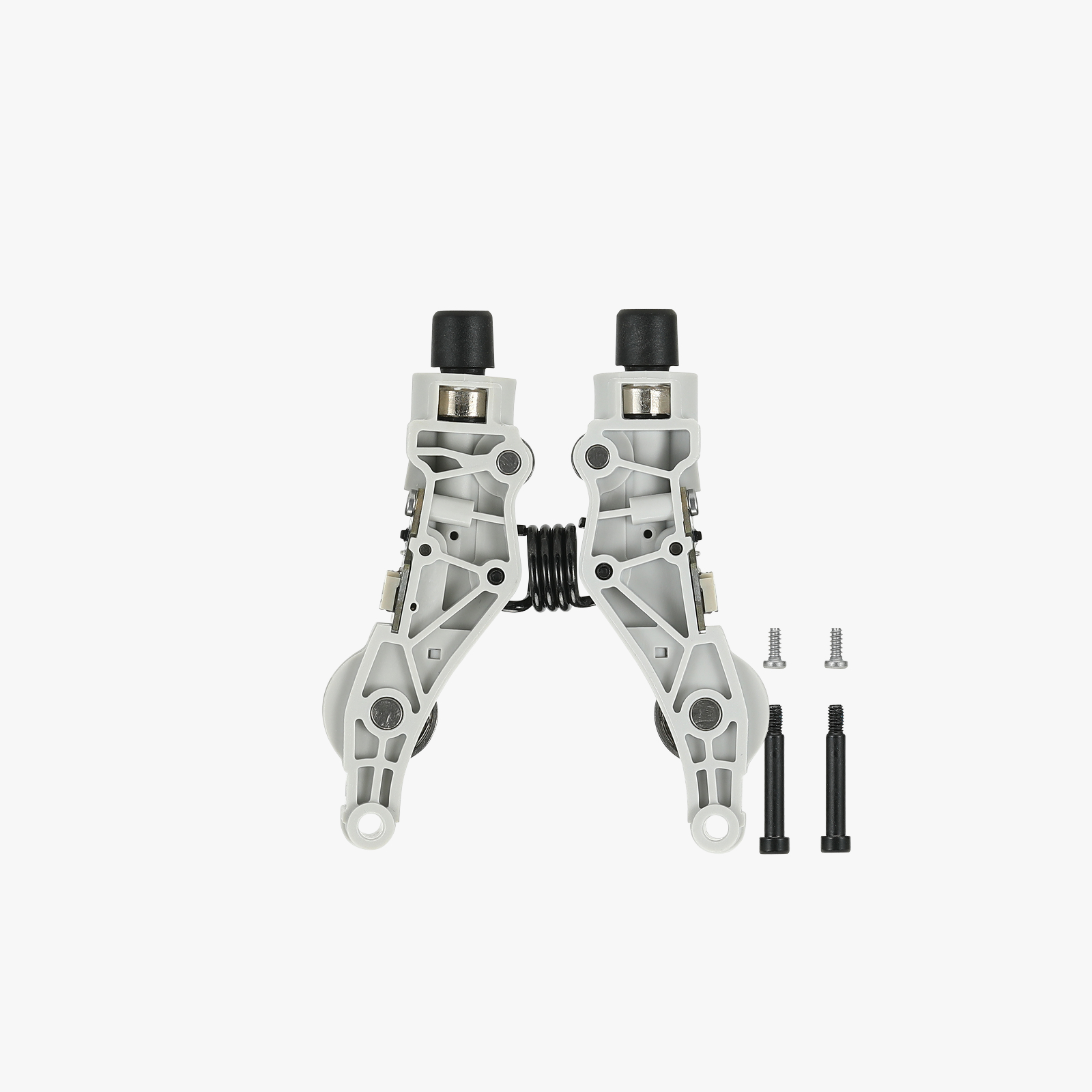
The spare parts for the dual extruder idlers and filament sensor include the following:&##x20;
1.Dual extruder idlers and filament sensor * 1
2.BT2x5 screw * 2
3.M2.5x19x5 screw * 2
When to Use
The dual extruder idlers and filament sensor are damaged.
Tools and Materials Needed
1.New dual extruder idlers and filament sensor&##x20;
2.H2.0 Allen key
3.H1.5 Allen key
4.Tweezers
Safety Warning
IMPORTANT!
It's crucial to power off the printer before conducting any maintenance work, including work on the printer's electronics and tool head wires. Performing tasks with the printer on can result in a short circuit, leading to electronic damage and safety hazards.
During maintenance or troubleshooting, you may need to disassemble parts, including the hotend. This exposes wires and electrical components that could short circuit if they contact each other, other metal, or electronic components while the printer is still on. This can result in damage to the printer's electronics and additional issues.
Therefore, it's crucial to turn off the printer and disconnect it from the power source before conducting any maintenance. This prevents short circuits or damage to the printer's electronics, ensuring safe and effective maintenance. For any concerns or questions about following this guide, we recommend submitting a technical ticket regarding your issue and we will do our best to respond promptly and provide the assistance you need.
Remove the Dual Extruder Idlers and Filament Sensor
Step 1: Remove the quick change tool interface&##x20;
You can refer to this Wiki to remove the quick change tool interface, which will facilitate the removal of the dual extruder idlers and filament sensor: Replace H2D Quick Change Tool Interface
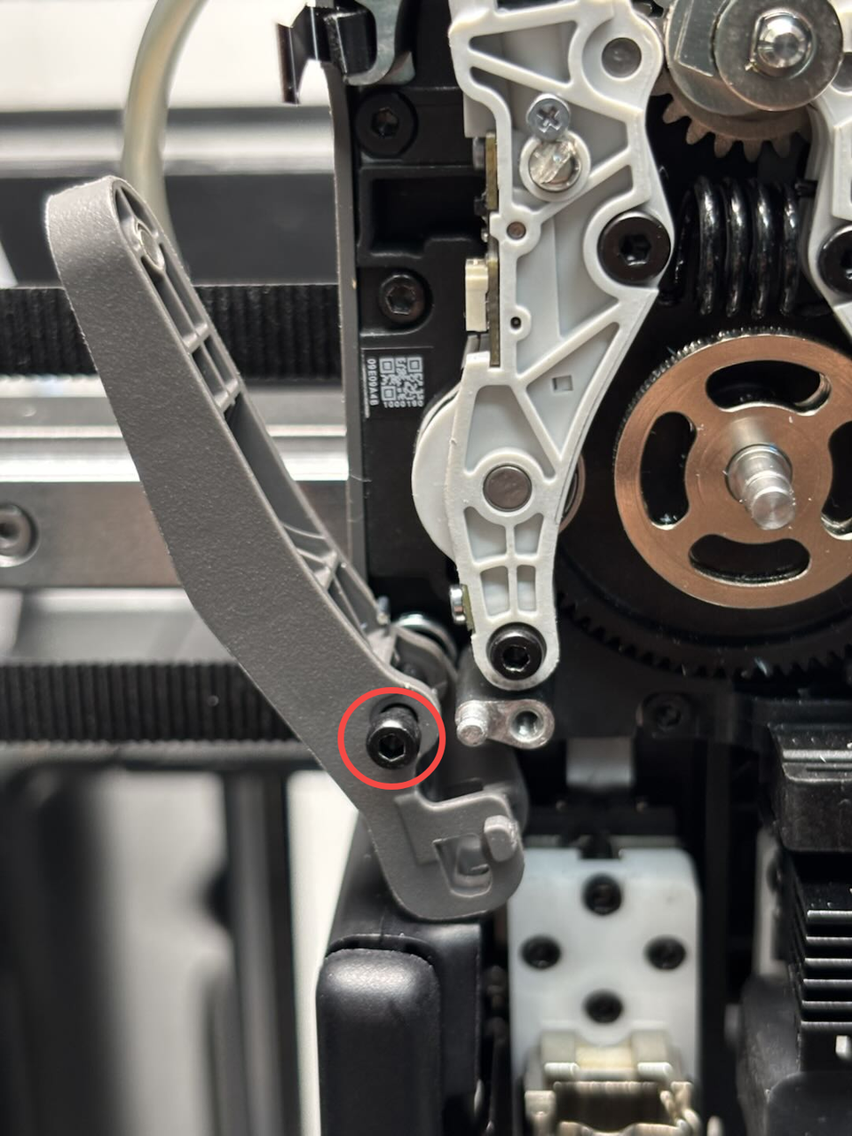
Step 2: Remove the left cutter
Since the left cutter blocks the fixing screws for the hall sensor FPC, we recommend removing the left cutter first to facilitate the removal of the dual extruder idlers and filament sensor.
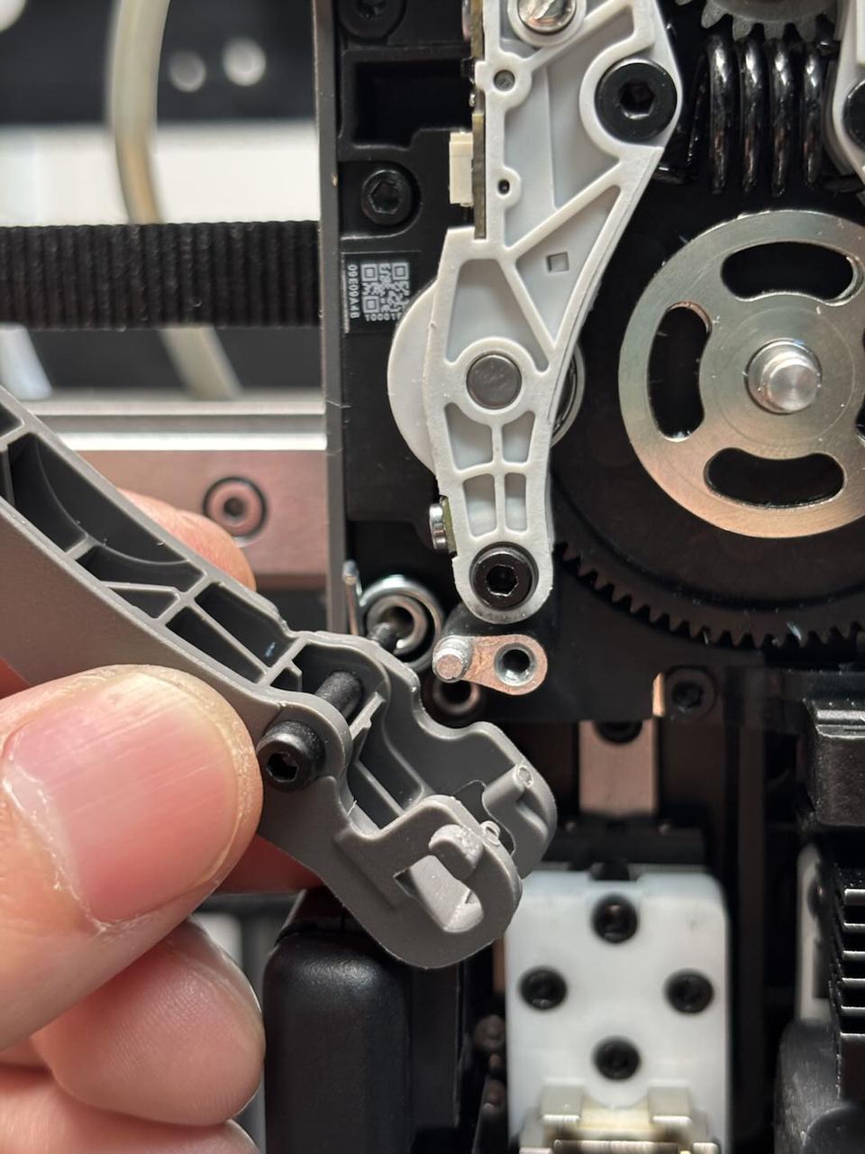
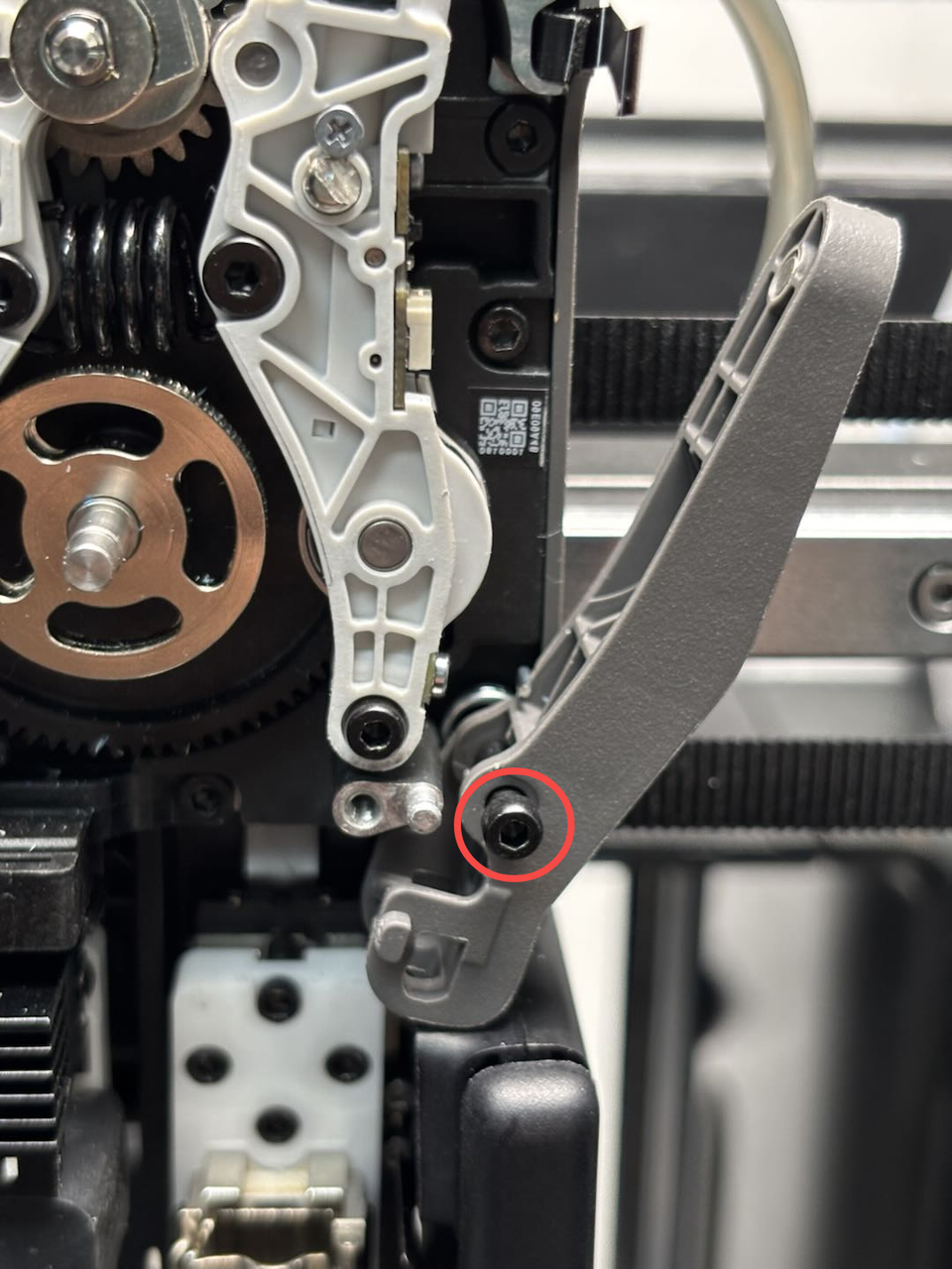
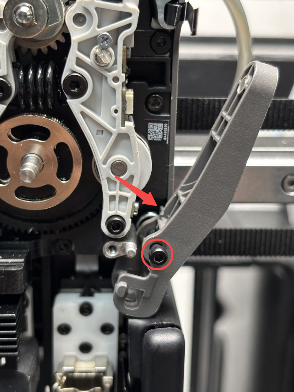
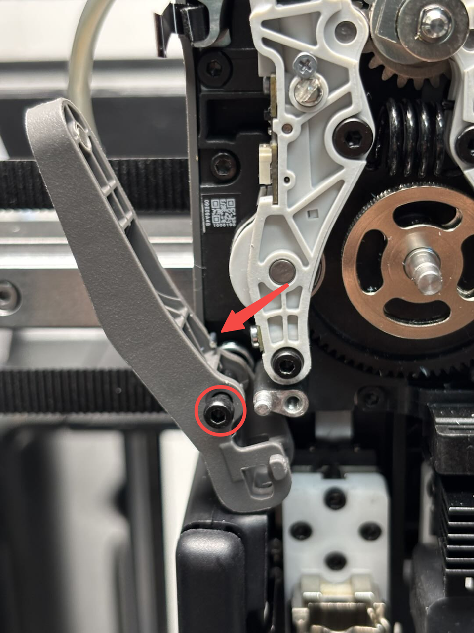
Use an H2.0 Allen key to remove one fixing screw, then take out the cutter, screw, and torsion spring together from the extruder.
Step 3: Remove the right cutter
Use an H2.0 Allen key to remove one fixing screw, then take out the cutter, screw, and torsion spring together from the extruder.
Step 4: Remove the dual extruder idlers and filament sensor
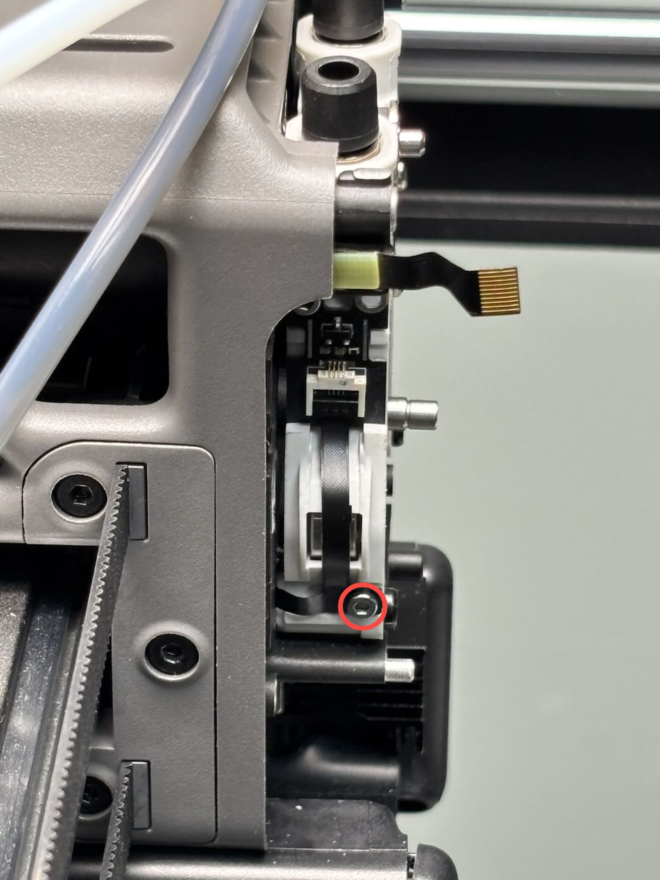
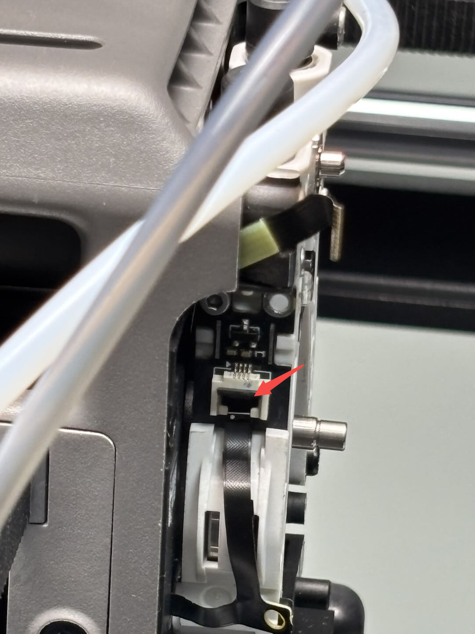
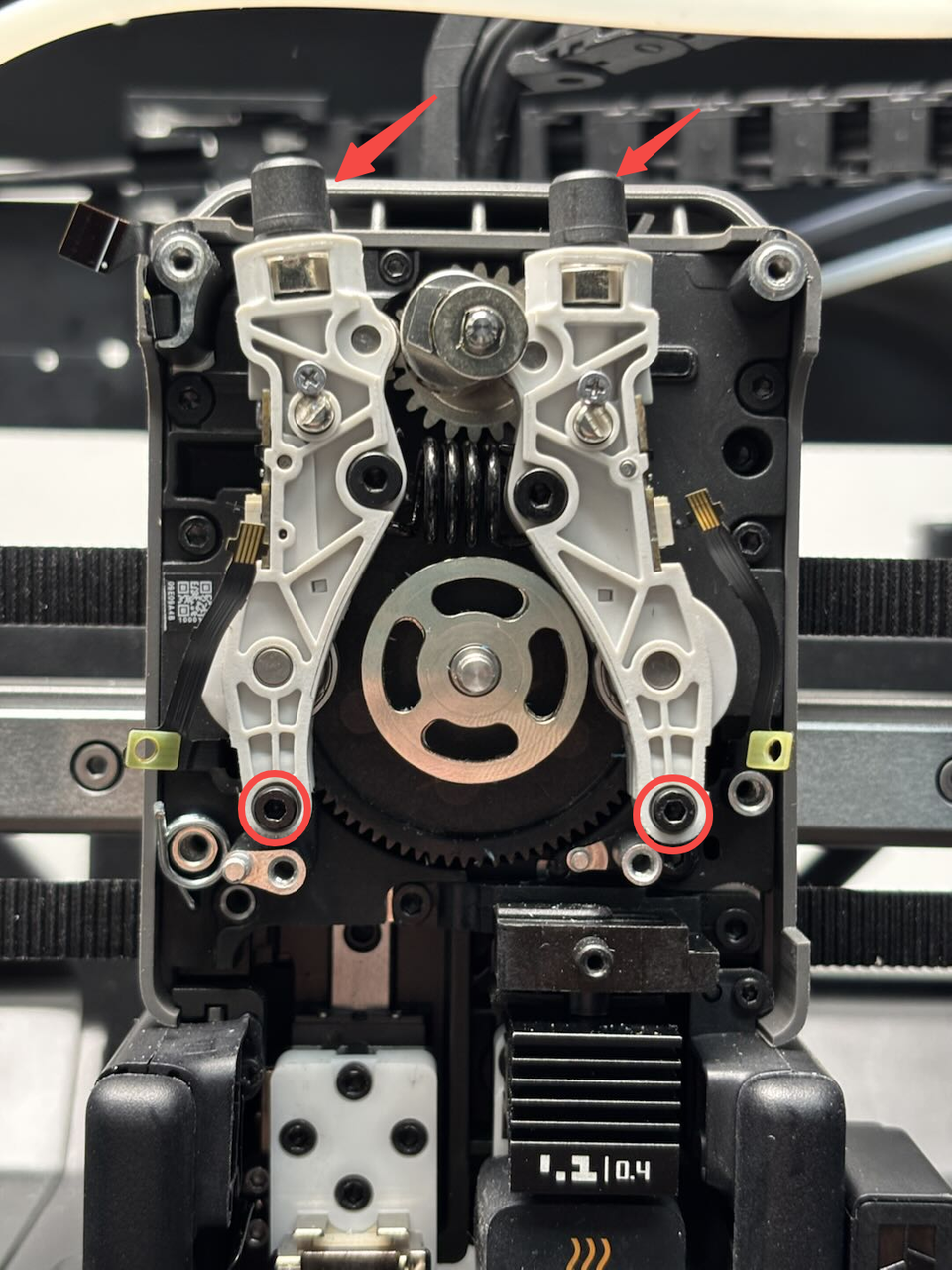
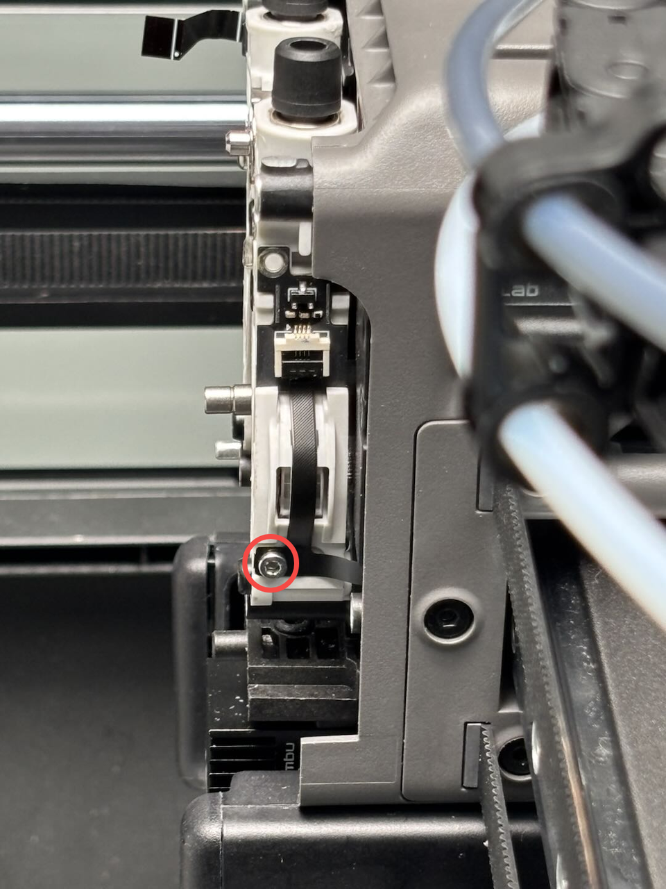
1.Use an H1.5 Allen key to remove the hall sensor FPC fixing screws (BT2x5) on both sides of the dual extruder idlers and filament sensor, then disconnect the hall sensor FPCs and remove the dual extruder idlers and filament sensor.


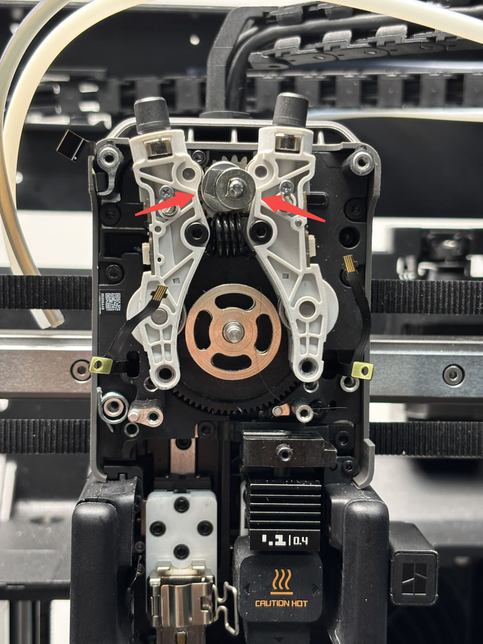
Press the pneumatic connector at the top to remove the 2 PTFE tubes, then use an H2.0 Allen key to remove the 2 fixing screws. Push the dual extruder idlers and filament sensor upward slightly, then remove it.

Install the Dual Extruder Idlers and Filament Sensor
Step 1: Install the dual extruder idlers and filament sensor
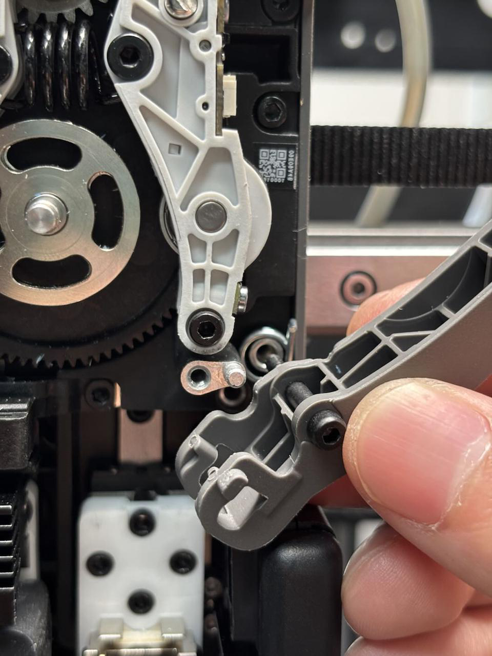
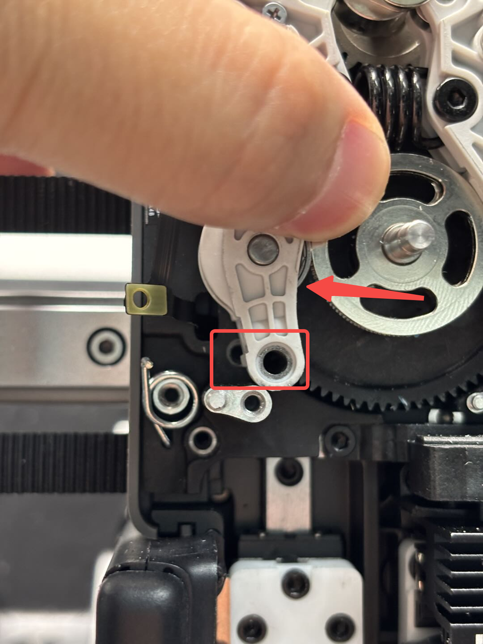
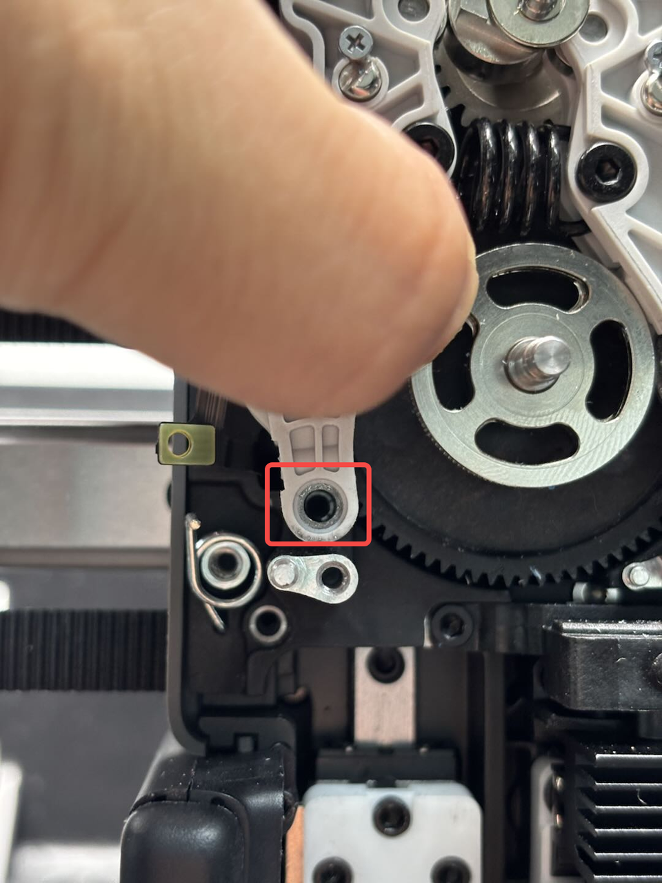
1.Position the dual extruder idlers and filament sensor with the screw side facing you, then pull the torsion spring and engage the dual extruder idlers and filament sensor into the cam. Press it down until it clicks into place.


Gently push the bottom of the idler to align the screw holes with the extruder rear cover, then insert the screws and tighten them using an H2.0 Allen key. Repeat the process for the other side.
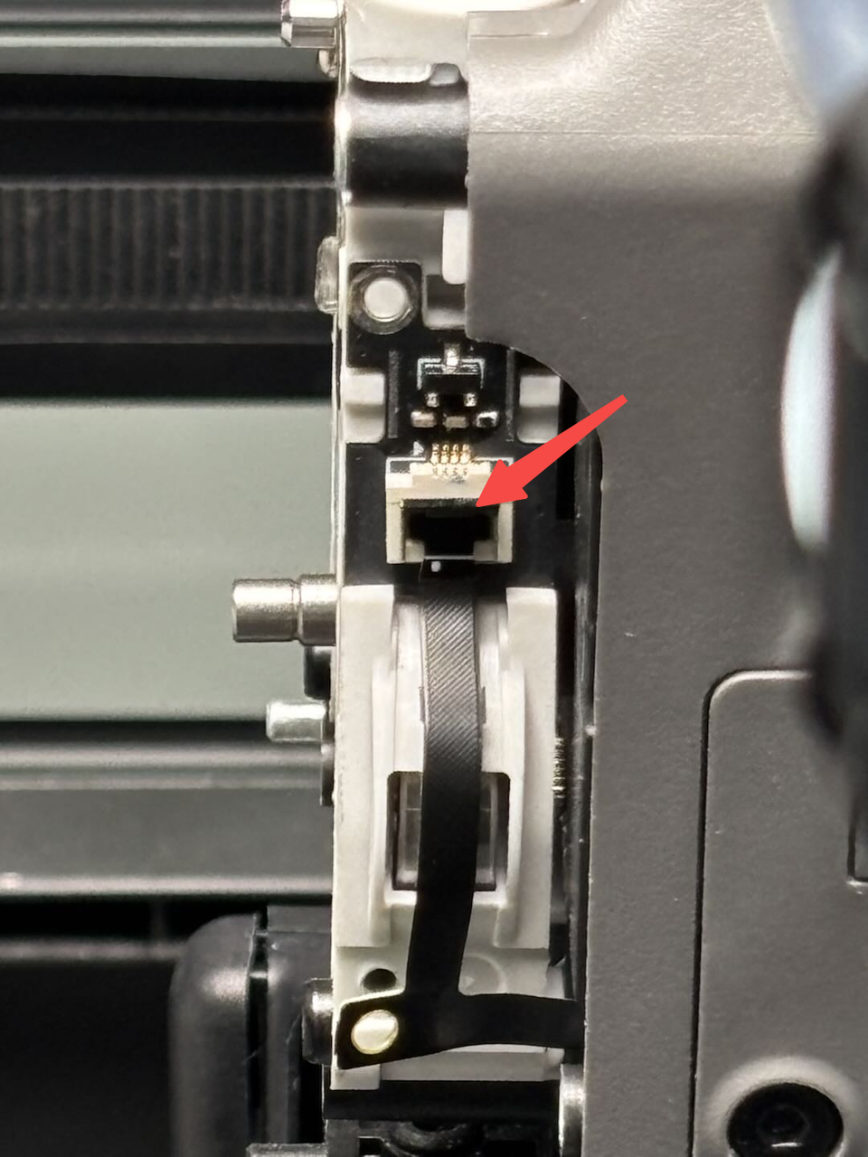
 Use an H1.5 Allen key to tighten the hall sensor FPC fixing screws on both sides, then insert the left and right hall sensor FPCs into the connectors on the dual extruder idlers and filament sensor and lock the buckles.


Step 2: Install the right cutter
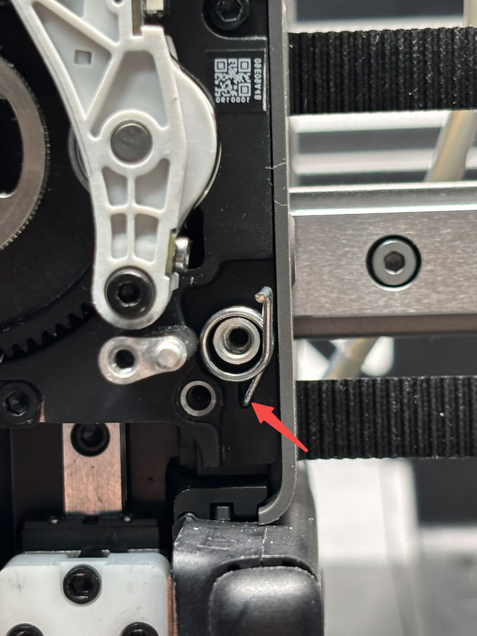
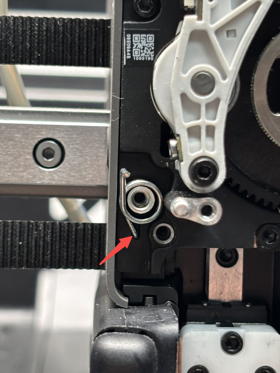
First, insert the torsion spring, with the other end fitting into the small hole on the extruder rear cover. Pass the screw through the cutter lever, engage the torsion spring inside the cutter lever, and finally align the screw hole and tighten it using an H2.0 Allen key.

Step 3: Install the left cutter
Similar to the step 2 above, insert the torsion spring, with the other end fitting into the small hole on the extruder rear cover. Pass the screw through the cutter lever, engage the torsion spring inside the cutter lever, and finally align the screw hole and tighten it using an H2.0 Allen key.

Step 4: Install the quick change tool interface
You can refer to this Wiki to install the quick change tool interface:
Replace H2D Quick Change Tool Interface
Verify the Functionality
Connect the power and turn on the printer. Operate the hotend switch on the screen to check if it switches successfully.