


Bambu Lab H2C Vortek Hotend Rack Belt Assembly
Couldn't load pickup availability
Use this text to encourage communication or promote sharing on social networks.
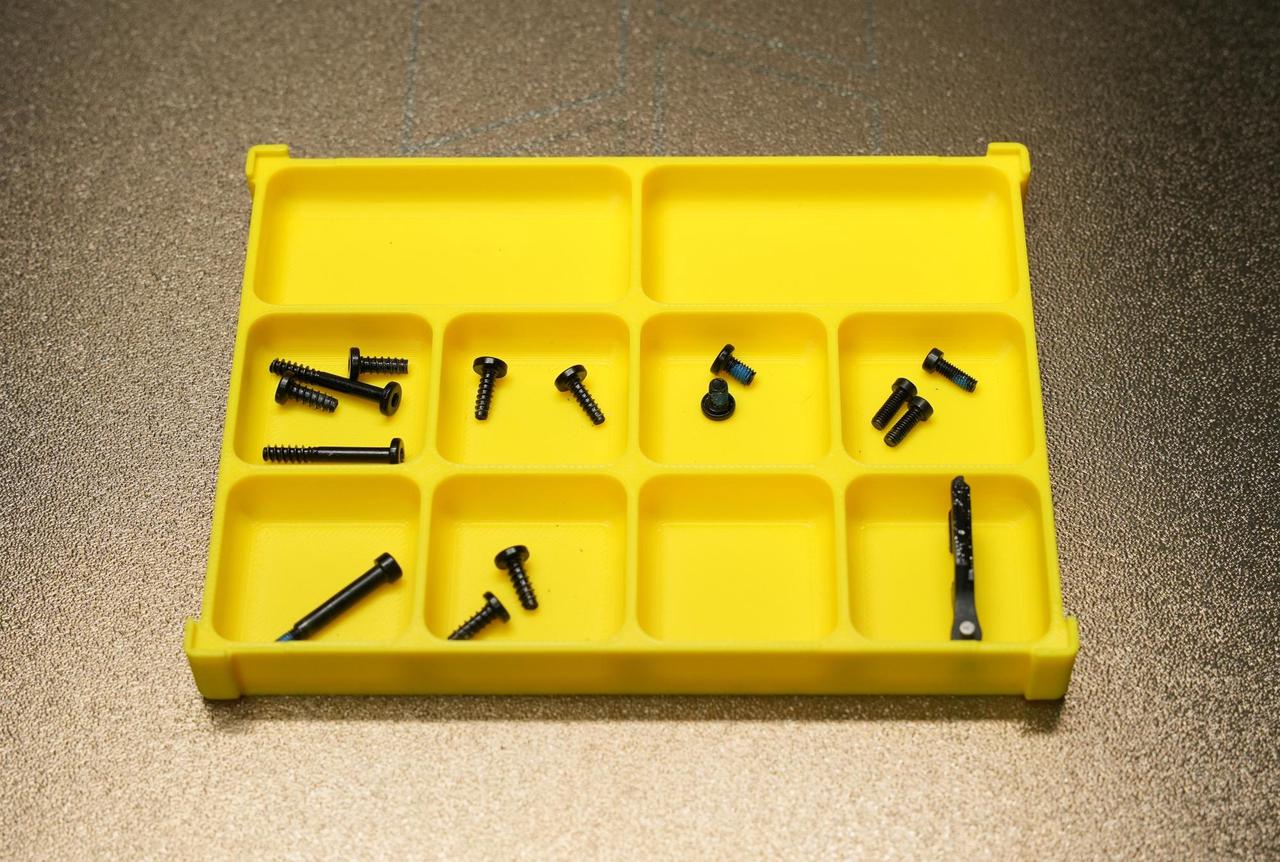
This replacement process involves many screws. To prevent loss or mix-ups, it is recommended to prepare a screw storage box in advance for classification and easy retrieval.
Perfect accessories, easy installation, perfect upgrades and replacement parts.
Vortek Hotend Rack Belt Assembly
The Induction Hotend Rack Belt Assembly is the power transmission core of the Vortek system. It transfers the rotational motion generated by the 3513 Induction Hotend Rack Motor into precise linear lifting motion of the induction hotend rack.
When to Use this Guide
The belt is damaged or broken
Bambu technical support has advised replacement
Required Tools and Materials
H1.5 screwdriver
H2.0 screwdriver
This replacement process involves many screws. To prevent loss or mix-ups, it is recommended to prepare a screw storage box in advance for classification and easy retrieval.
Safety Warning
It's crucial to power off the printer before conducting any maintenance work, including work on the printer's electronics and tool head wires. Performing tasks with the printer on can result in a short circuit, leading to electronic damage and safety hazards.
During maintenance or troubleshooting, you may need to disassemble parts, including the hotend. This exposes wires and electrical components that could short circuit if they contact each other, other metal, or electronic components while the printer is still on. This can result in damage to the printer's electronics and additional issues.
Therefore, it's crucial to turn off the printer and disconnect it from the power source before conducting any maintenance. This prevents short circuits or damage to the printer's electronics, ensuring safe and effective maintenance. For any concerns or questions about following this guide, open a new ticket in our Support Page and we will do our best to respond promptly and provide the assistance you need.
Removing the Old Induction Hotend Rack Belt Assembly
Step 1: Remove the Induction Hotend Latch Actuator
Disconnect the cable of the induction hotend rack belt assembly, then use a 2.0 mm screwdriver to remove the three fixing screws and detach the assembly. For detailed replacement steps, please refer to the wiki: Replacing the Induction Hotend Latch Actuator.
Step 2: Remove the Induction Hotend Rack Assembly
For detailed replacement steps, please refer to the wiki:,Induction Hotend Rack Assembly Replacement Guide.
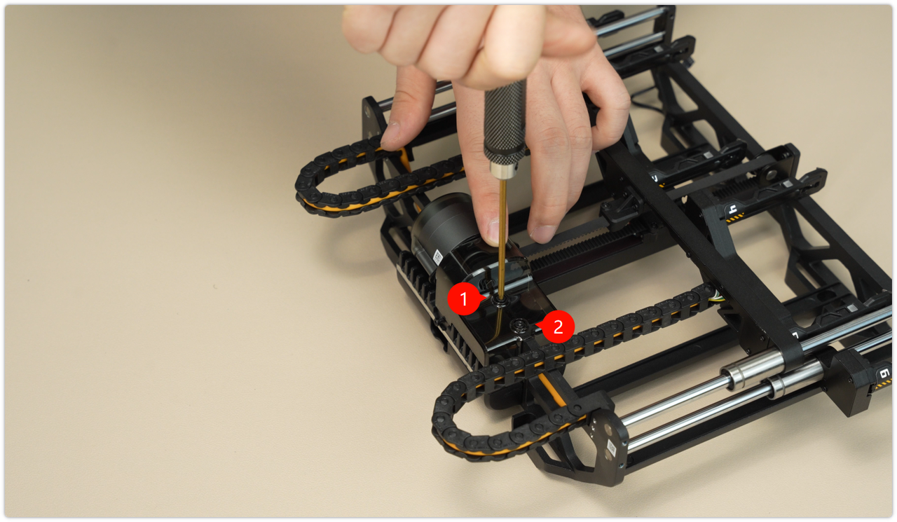
Step 3: Remove the Protective Cover for the Induction Hotend Motor
Use a 2.0 mm screwdriver to remove the two screws, then take off the protective cover of the induction hotend bracket motor.
 Step 4: Remove the Induction Hotend Rack Belt Assembly
 For detailed replacement steps, please refer to the wiki: Induction Hotend Rack Assembly Replacement Guide.
Step 5: Install the Induction Hotend Latch Actuator
When tightening the screws, take care to avoid the connecting cables to prevent excessive pressure from affecting communication.
For detailed replacement steps, please refer to the wiki: Induction Hotend Latch Actuator Replacement Guide.
Induction Hotend Rack Assembly Calibration
After reinstalling the hotend assembly, you need to perform calibration promptly to ensure printing accuracy. Follow the steps below to do so:
1. On the printer screen, tap Settings on the left sidebar → open the "Calibration" menu, and select "Induction Hotend Rack Setup".
2. Click Start, and the induction hotend rack setup will automatically run the preset initialization process.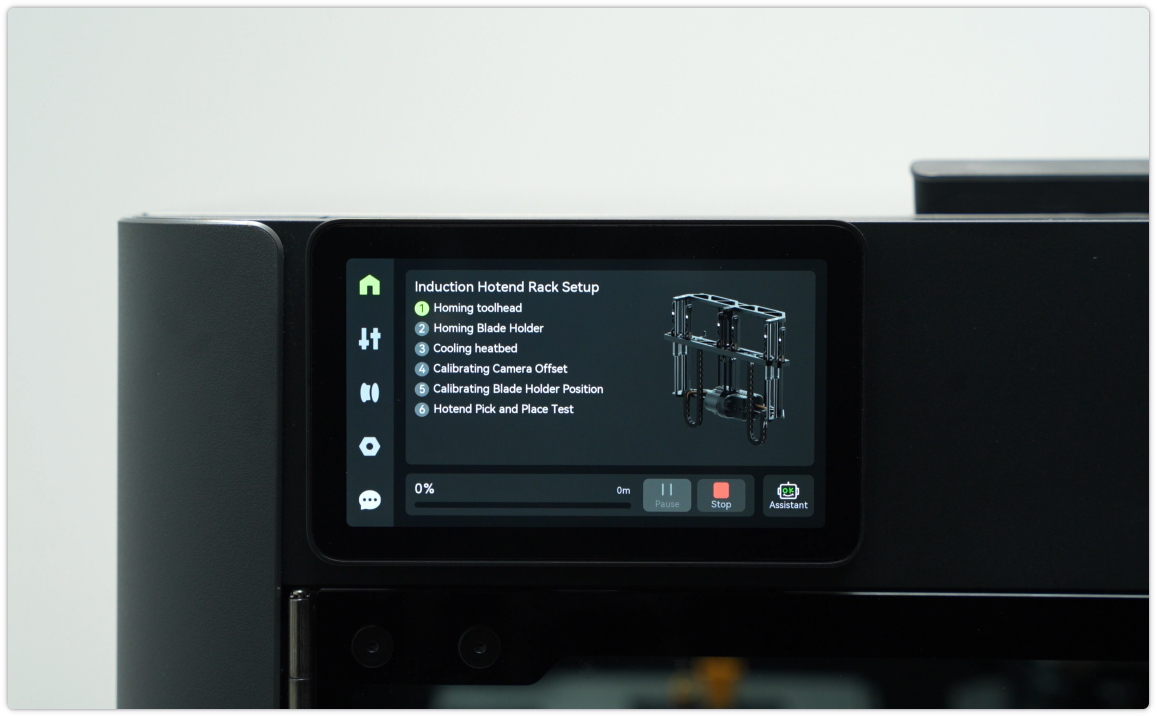 Troubleshooting: If an error or failure occurs during initialization, it is likely that the installation deviation of the induction hotend rack assembly exceeds the allowable tolerance. Please refer to the H2C Induction Hotend Rack Manual Position Calibration Guide to re-calibrate the manual position. After completion, you can try the calibration operation again.
Verifying Functionality
Connect the power supply and turn on the printer to verify that the induction hotend can be picked up and placed correctly, and that its information can be read normally.