


Auxiliary Hotend Heating Assembly - Right /Left for Bambu X2D
Couldn't load pickup availability
Use this text to encourage communication or promote sharing on social networks.
Auxiliary Hotend Heating Assembly - Right
The right hotend heating assembly is installed on the toolhead for the right hotend, and is responsible for heating the nozzle.
In the Box
- Right Auxiliary Hotend Heating Assembly *1
Compatibility
X2D
Hotend Heating Assembly - Left
The left hotend heating assembly is installed on the toolhead for the left hotend, and is responsible for heating the nozzle.
In the Box
- Left Hotend Heating Assembly *1
Compatibility
X2D
Hotend Heating Assembly Replacement guide for the X2D
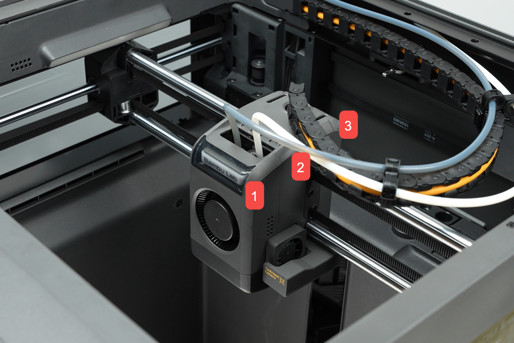
Hotend heating assembly
The hotend heating assembly is installed on the toolhead and is responsible for heating the printing filament to a molten state.
The X2D toolhead is equipped with two hotend heating assemblies: the left hotend heating assembly and the right auxiliary hotend heating assembly, which are not interchangeable.If one is damaged, you need to first identify which heating assembly is faulty to avoid purchasing the wrong part.

The left hotend heating assembly replacement kit includes:
1.Left hotend heating assembly
2.Fixing Screws ( x3 )
The right auxiliary hotend heating assembly replacement kit includes:
1.Right auxiliary hotend heating assembly
2.Fixing Screws ( x3 )
Applicable printer model
Bambu Lab X2D
When to Replace
Abnormal hotend heating function indicates a possible malfunction.
Damage to the hotend heating assembly cable affects the printer's operation.
Obvious physical damage to the hotend heating assembly caused by improper operation or external impact may affect its functionality.
Bambu Lab technical support recommends replacing the hotend heating assembly based on diagnostic results.
Required Tools and Materials
New hotend heating assembly
H1.5 allen key
H2.0 allen key
Safety Warning
⚠️ IMPORTANT!
It's crucial to power off the printer before conducting any maintenance work, including work on the printer's electronics and tool head wires. Performing tasks with the printer on can result in a short circuit, leading to electronic damage and safety hazards.
During maintenance or troubleshooting, you may need to disassemble parts, including the hotend. This exposes wires and electrical components that could short circuit if they contact each other, other metal, or electronic components while the printer is still on. This can result in damage to the printer's electronics and additional issues.
Therefore, it's crucial to turn off the printer and disconnect it from the power source before conducting any maintenance. This prevents short circuits or damage to the printer's electronics, ensuring safe and effective maintenance.
Remove the hotend heating assembly
Step 1. Remove the toolhead housing
Step 2. Remove the hotend

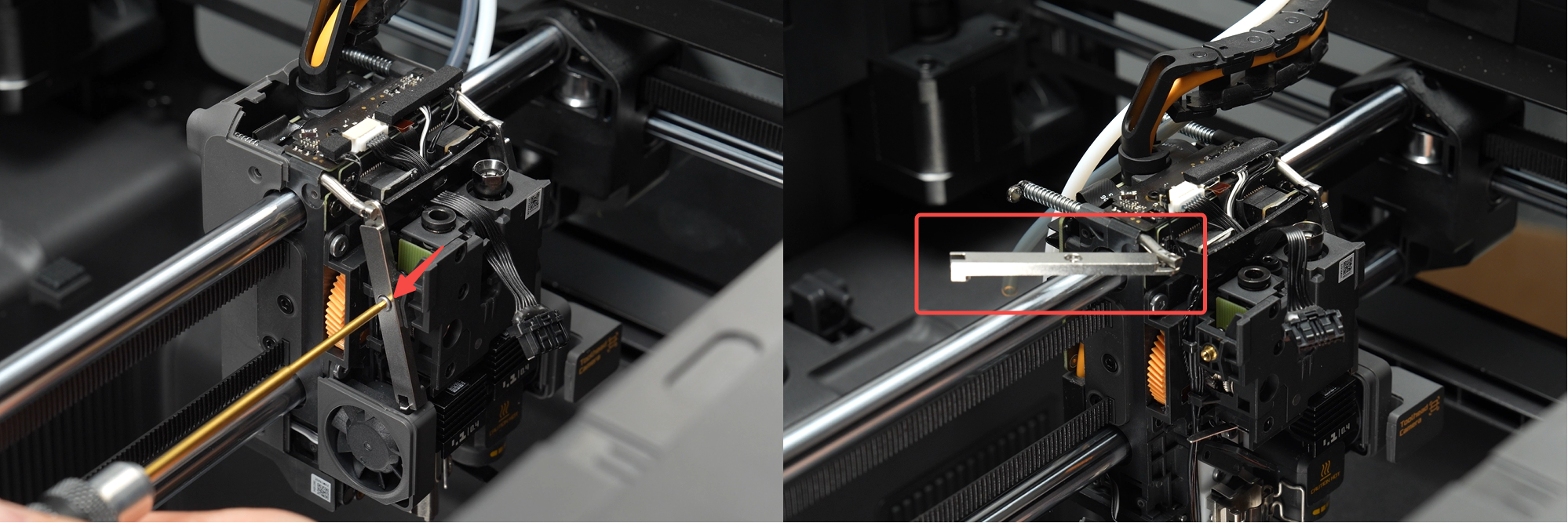
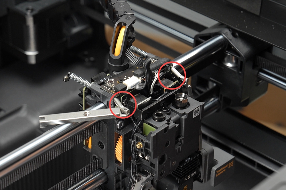
Step 3. Loosen the filament cutter lever
Use an H1.5 allen key to remove one screw each on the left and right filament cutter levers to separate the lever from the filament cutter assembly. Rotate the lever and nest it on the X-Axis linear shaft.
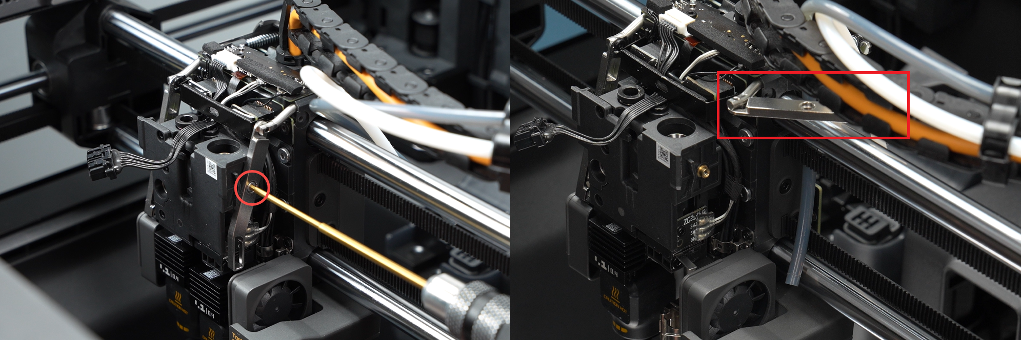
Step 4. Remove the hotend heating assembly connector bracket
Use an H1.5 allen key to remove the two screws fixing the hotend heating assembly connector retaining clip, then remove the bracket.
Steps 5~6 are only for removing the left hotend heating assembly. If only replacing the right auxiliary hotend heating assembly, you may skip to Step 7.
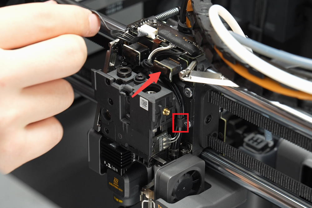
Step 5. Disconnect the left hotend heating assembly cable
Disconnect the left hotend heating assembly connector and remove the cable from the locking tab.
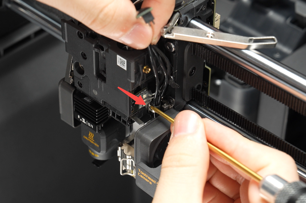
Step 6. Remove the left hotend heating assembly
Use an H2.0 allen key to remove the three screws securing the left hotend heating assembly, then take off the assembly.
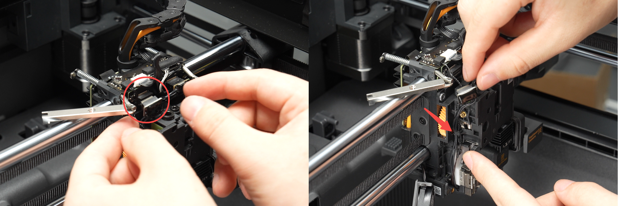
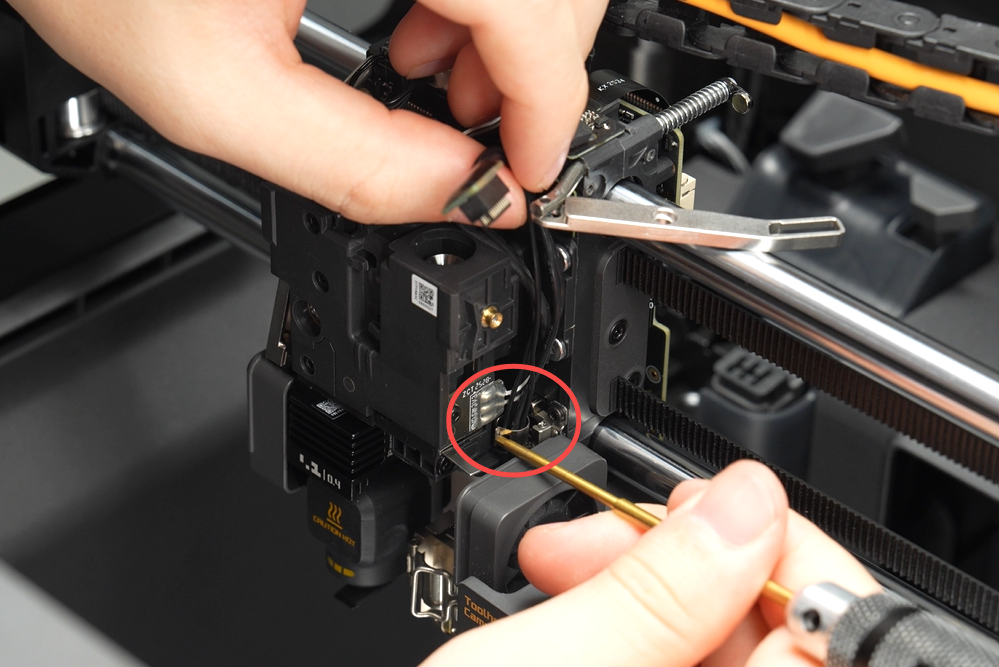
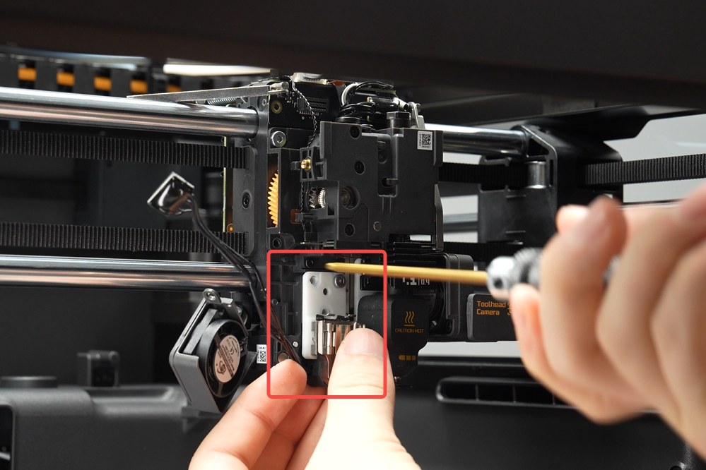
Step 7. Disconnect the right auxiliary hotend heating assembly cable
1.Disconnect the right auxiliary hotend heating assembly connector and remove the tape securing the cable.
2.Press one side of the metal cable locking tab with an allen key to release it, then remove the hotend heating assembly cable.
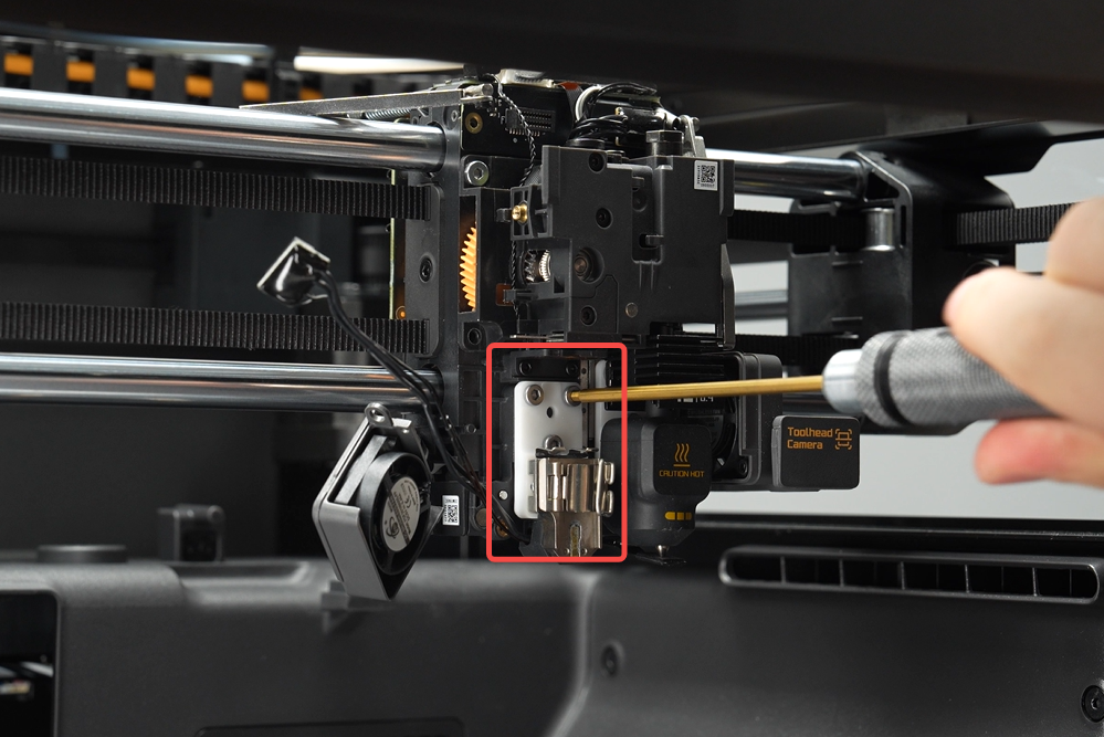
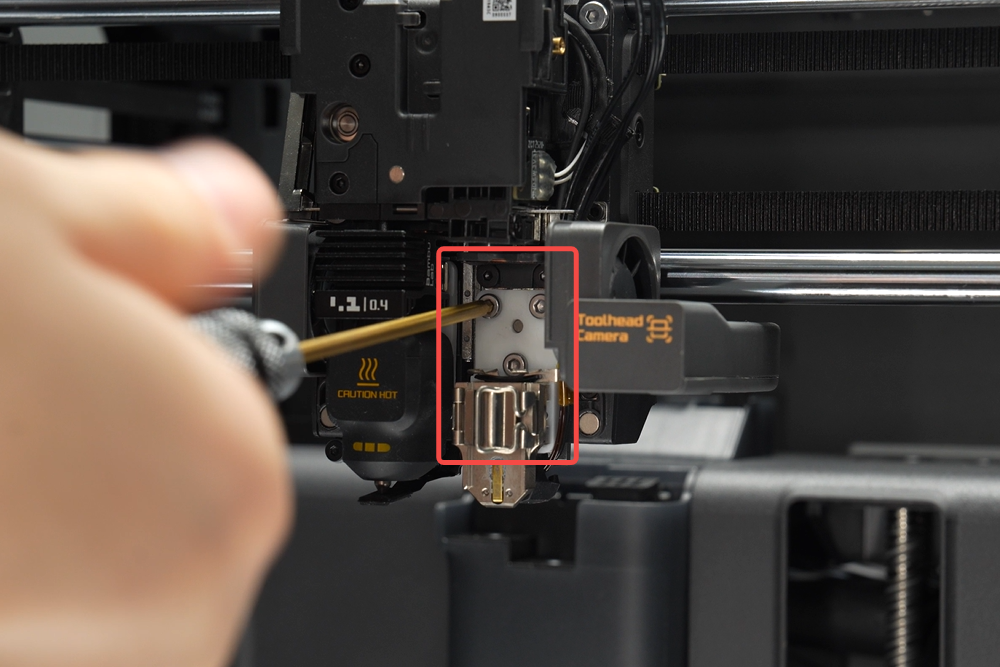
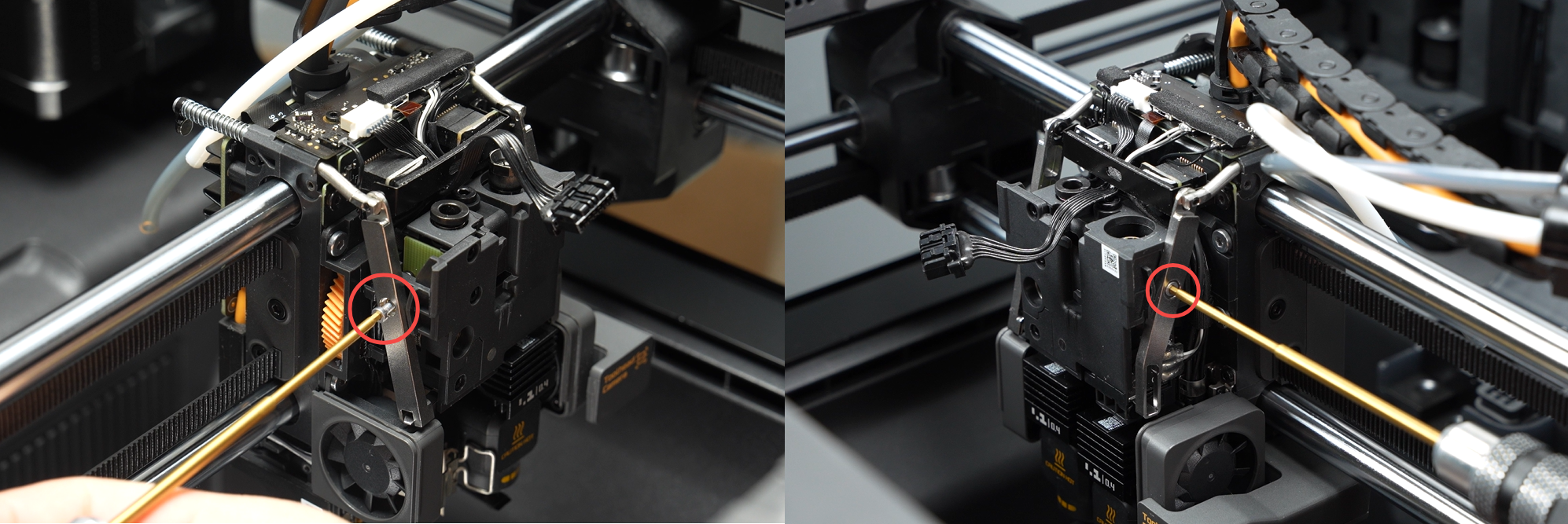
Step 8. Remove the right auxiliary hotend heating assembly
Use an H2.0 allen key to remove the three screws securing the right auxiliary hotend heating assembly, then remove the assembly.
Install the hotend heating assembly
ℹ️ Note: Steps 1~2 cover installing the right auxiliary hotend heating assembly. If only installing the left hotend heating assembly, you may skip to Step 3.
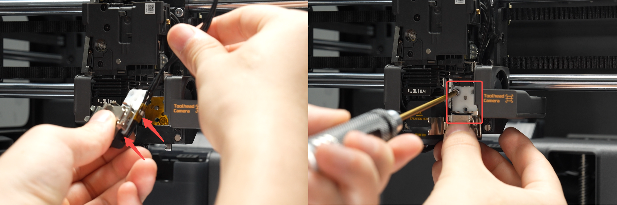
Step 1. Install the right auxiliary hotend heating assembly
Secure the hotend heating assembly cable into the right locking tab, then install the right auxiliary hotend heating assembly onto the toolhead. Use an H2.0 allen key to tighten the three mounting screws.
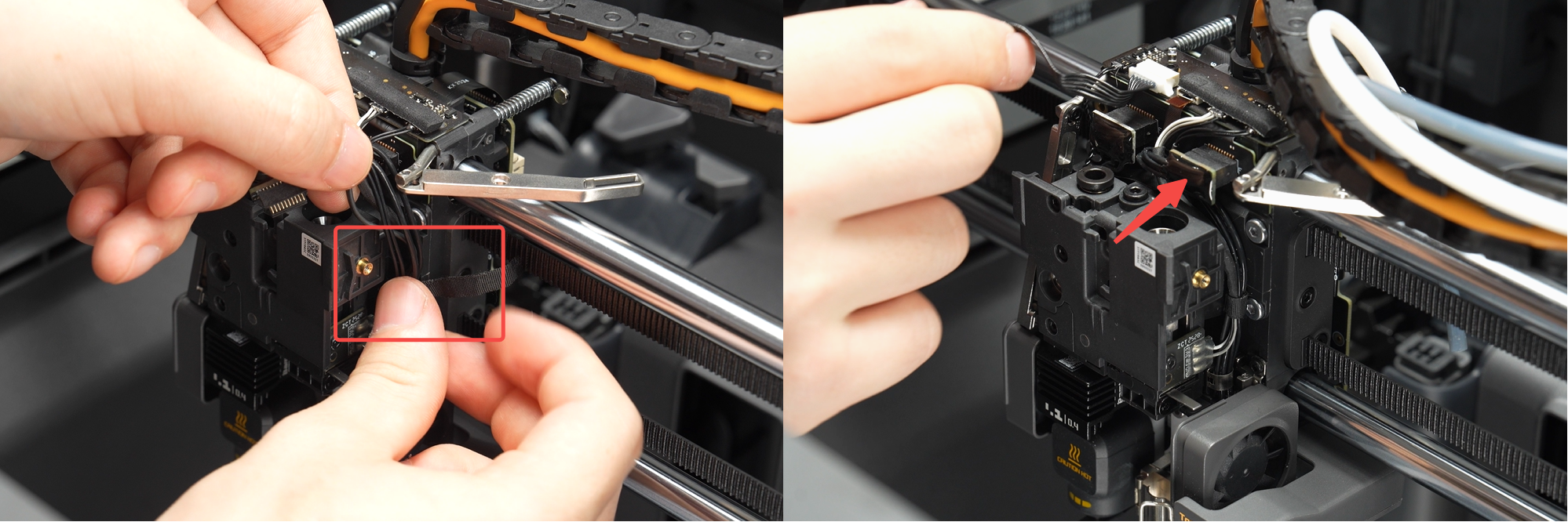
Step 2. Secure the right auxiliary hotend heating assembly cable
1.Position the cable at the center of the metal groove, place one side of the metal locking tab into the groove, then press the other side with an allen key to secure the locking tab inside the groove.
2.Wrap the securing tape around the cable, organize it to lie closely along one side of the toolhead block, and connect the cable plug to the hotend heating assembly interface board.
Step 3. Install the left hotend heating assembly
Route the hotend heating assembly cable from the side of the heating base, then install the assembly onto the toolhead (ensure the cable is not pinched beneath the hotend heating base!), and tighten the three mounting screws using an H2.0 allen key.
Step 4. Secure the left hotend heating assembly cable
Organize the cable and place it into the locking tab, then connect the cable plug to the hotend heating assembly interface board.

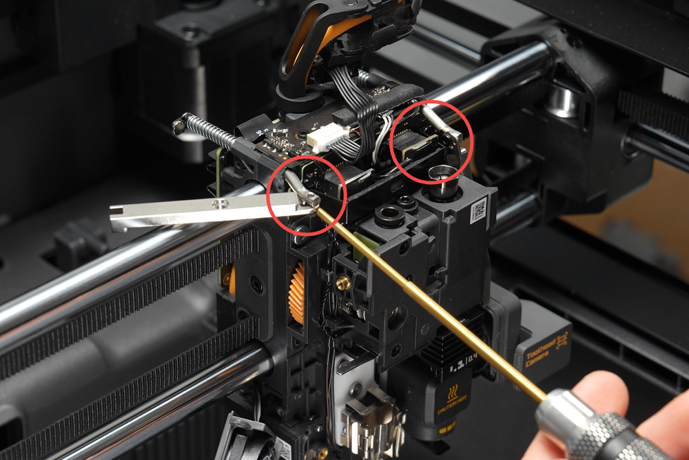
Step 5. Install the hotend heating assembly connector bracket
Install the hotend heating assembly connector bracket and tighten the two screws using an H1.5 allen key.
Step 6. Install the filament cutter lever
Use an H1.5 allen key to secure one screw each on the left and right filament cutter levers.
Step 7. Install the hotend

Step 8. Install the toolhead housing
Verifying Success
✅ Connect the power and turn on the printer. Heat the hotend to 100℃ to confirm normal temperature rise.
If you encounter any issues, please retrace your steps and check all connections before trying again. If the problems persist, please contact the Bambu Lab service team for further assistance.